EasyManua.ls Logo

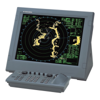
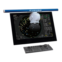
Furuno FAR-2107 Series User Manual

Furuno FAR-2107 Series
52 pages
To Next Page IconTo Next Page
Page #1 background imageLoading...
Page #1 background image
www.furuno.co.jp
All brand and product names are trademarks, registered trademarks or service marks of their respective holders.
MARINE RADAR
FAR-2107/FAR-2807 SERIES
Operators Manual:
Fishing Vessel Specifications
The purpose of this manual is to provide the operating procedures for the functions available with
the fishing vessel specifications models (50 kW and 60 kW models) of the FAR-2107/FAR-2807
series radar. This manual is provided in addition to the Operator's Manual, which covers features
common to all radars in this radar series.
Specification type is set during installation. For details, contact a FURUNO agent or dealer.
Operation from the menu involves spinning the scrollwheel to select menu item or option then
pushing the scrollwheel or left button to confirm selection. For sake of brevity, we write "Select
XXX" (XXX=name of menu item) when you would spin the scrollwheel to make a selection and
"push the left button" when you confirm selection.
Contents
1. TARGET TRAIL FUNCTIONS................... 2
1.1 Long Trails....................................................2
1.2 Trail Color.....................................................3
1.3 Trail Color Shift.............................................4
1.4 Hiding Trails .................................................5
1.5 Trail Eraser...................................................6
1.6 Narrow Trails................................................7
1.7 Preventing True Sea Clutter Trails...............7
2. CURSORS ................................................. 8
2.1 Crosshairs Cursor Size ................................8
2.2 Net Cursor....................................................9
2.3 Cursor Data Display ...................................11
2.4 Bearing Scale Format.................................12
3. OTHER FUNCTIONS............................... 13
3.1 Echo Display Area......................................13
3.2 Turning On-screen Boxes On/Of................14
3.3 Radar Picture Color....................................15
3.4 Bearing Reference .....................................16
3.5 VRM, Cursor Unit .......................................17
3.6 Pop-up Guidance .......................................17
4. FUNCTION KEYS (F1 - F4) .....................18
4.1 F1, F2 and F3 Keys.................................... 18
4.2 Operating the F4 Key................................. 27
5. ANCHOR WATCH ALARM......................31
6. VIDEO PLOTTER FUNCTIONS...............32
6.1 Depth Contour with Depth Indication ......... 32
6.2 Mark Settings .............................................33
6.3 Track Settings ............................................36
6.4 GPS Buoy ..................................................41
7. ARP SYMBOLS .......................................42
8. DISPLAYING PICTURE FROM
EXTERNAL RADAR ................................43
9. MENU TREE.............................................44

Other manuals for Furuno FAR-2107 Series

Question and Answer IconNeed help?

Do you have a question about the Furuno FAR-2107 Series and is the answer not in the manual?

Furuno FAR-2107 Series Specifications

General IconGeneral
Display TypeLCD
Frequency9410 MHz
Antenna TypeSlotted Waveguide
Rotation Speed24 or 48 rpm
Input Voltage24 V DC
Antenna Length6 feet

Summary

Target Trail Functions

Long Trails

Selectable trail lengths including 12h, 24h, and 48h in addition to standard options.

Trail Color

Choose target trail colors from a predefined palette for enhanced visibility.

Trail Eraser

Allows erasing specific portions or wide areas of trails on the display to reduce clutter.

Cursors

Crosshairs Cursor Size

Adjust the size of the crosshairs cursor to small or large for better visibility.

Net Cursor

Depict fishing nets on the radar display by entering net dimensions for accurate representation.

Cursor Data Display

Configure display of cursor position, coordinates, range, and bearing from the ship.

Other Functions

Echo Display Area

Select echo display area configuration: CIRCLE, WIDE, or ALL for viewing targets.

Turning On-screen Boxes On/Off

Control the visibility of on-screen boxes and indications to avoid obscuring radar targets.

Radar Picture Color

Set radar echo display to single color or multicolor, with multicolor showing descending strength.

Bearing Reference

Select bearing reference for EBL and cursor: relative (R) or true (T).

Function Keys (F1 - F4)

F1, F2 and F3 Keys

Automate complex or repetitive tasks by programming functions to F1, F2, and F3 keys.

Operating the F4 Key

Program the F4 key as a macro for complex tasks, allowing up to ten programmed functions.

Anchor Watch Alarm

Video Plotter Functions

Depth Contour with Depth Indication

Display depth indications on depth contours within the plotter function.

Mark Settings

Enter marks to denote points of interest, with options for comments and position editing.

Track Settings

Configure track recording parameters, select track color, and erase tracks for own ship or targets.

GPS Buoy

Display information from GPS radio buoys, tracking net position or other monitored points.

ARP Symbols

Displaying Picture from External Radar

Menu Overview

Related product manuals