VR-3000 VOYAGE DATA RECORDER
VR-3000S SIMPLIFIED VOYAGE DATA RECORDER
Operator’s Guide
The purpose of this Operator's Guide is to provide basic operating procedures for this
equipment. For more detailed information see the Operator's Manual.
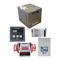
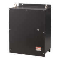
Data Collecting Unit (DCU)
Breaker switches (from left)
Battery Backup, DC, AC
Status Display
LEDs (from left)
SAVE (yellow):
Starts blinking from OFF state
when recording is stopped,
then lights steadily.
If the backup HDD is disconnected,
this LED lights also.
NORMAL (Green):
On at normal operation.
ERROR (red):
Lights for error.
LEDs: Light (green) when respective power is applied.
Backup HDD (inside)
HDD holder
Remote Alarm Panel (RAP)
LEDs (from left)
SAVE (yellow):
Starts blinking from OFF state
when recording is stopped,
then lights steadily.
If the HDD is disconnected,
this LED lights also.
NORMAL (Green):
On at normal operation.
ERROR (red):
Lights for error.
TEST: Tests LCD.
Status Display
DIMMER:
Adjust panel backlighting;
display software version
no. (pressed together).
Buzzer
ACK: Silences buzzer.
SAVE: Stops recording onto current memory area in the backup
HDD and starts recording onto another menory area.
--X: Indicates that X no. of recording
areas exist. (X: 4, 3, 2, 1)
---: Recording area is not yet known.
(at startup or when recognizing HDD)
www.furuno.com