•A common power supply regulator and diode may also be supplied with the speed controller, depend-
ing on the vehicle kit. Since they cause a voltage drop, always remove them.
TO BUYERS OF THE NEW ATTACK-BFR (FP-R102GF)
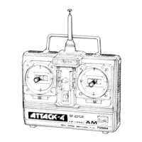
When using a Futaba motor control amp (MC-106,
106B, 108, 109, 110, etc.) instead of the speed
controller supplied with the vehicle, turn off the
ASP system as shown in the figure.
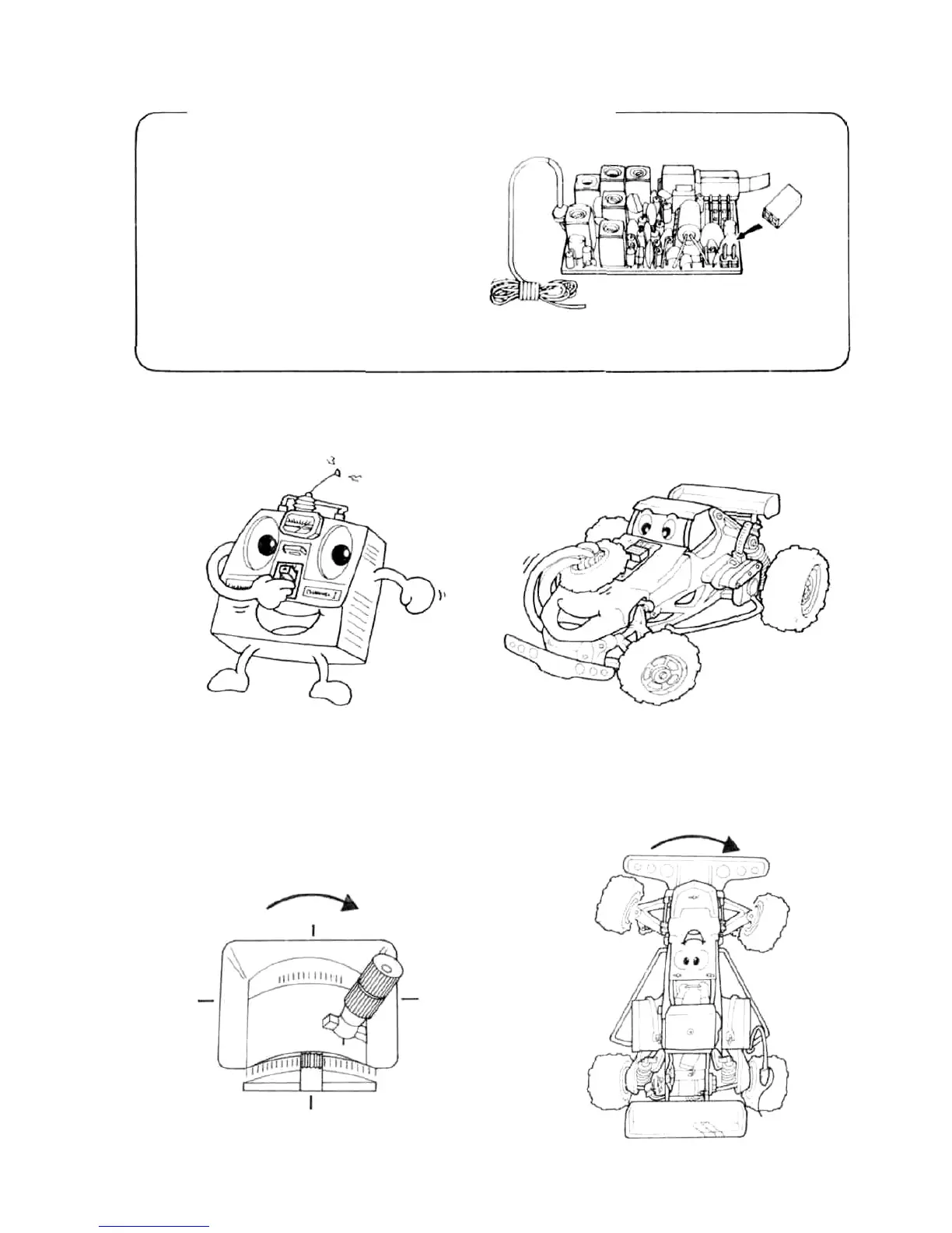
•Set the transmitter power switch to ON, then set the receiver power switch to ON. The servos stop near the neutral
position. Operate the transmitter sticks and check if each servo faithfully follows operation of the sticks.
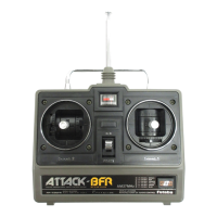
R102GF ASP
release
connector
Insert the ASP release co-
nnector packed with the
set at this 2P connector '
(male pins) on the printed
wiring board.
From transmitter
when switch turned
on
From receiver when
switch turned off
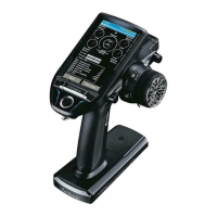
• Connect the pushrod to each servo horn, then check if the direction of travel of each servo matches the transmitter
operation.
When transmitter
stick lever set to the
right
Vehicle also steers
to the right
6