•Operate each servo over its full travel and check if the pushrod binds or is too loose. Applying unreasonable force to
the
servo
horn
will
adversely
affect
the
servo
and quickly drain
the
battery.
Be
especially
careful
when using
8.4V.
•Always make the full stroke (including trim) of the servo horns somewhat larger than the full travel. Adjust the
servo horns so that they move smoothly even when the trim lever and stick are operated simultaneously in the same
direction.
•
Be
alert for noise.
Always solder a noise killing capacitor to the running motor. If metal parts touch each other due to vibration, noise
will
be generated and
cause
the receiver
servos
to
operate erroneously.
We
recommend the
use
of
noiseless
parts.
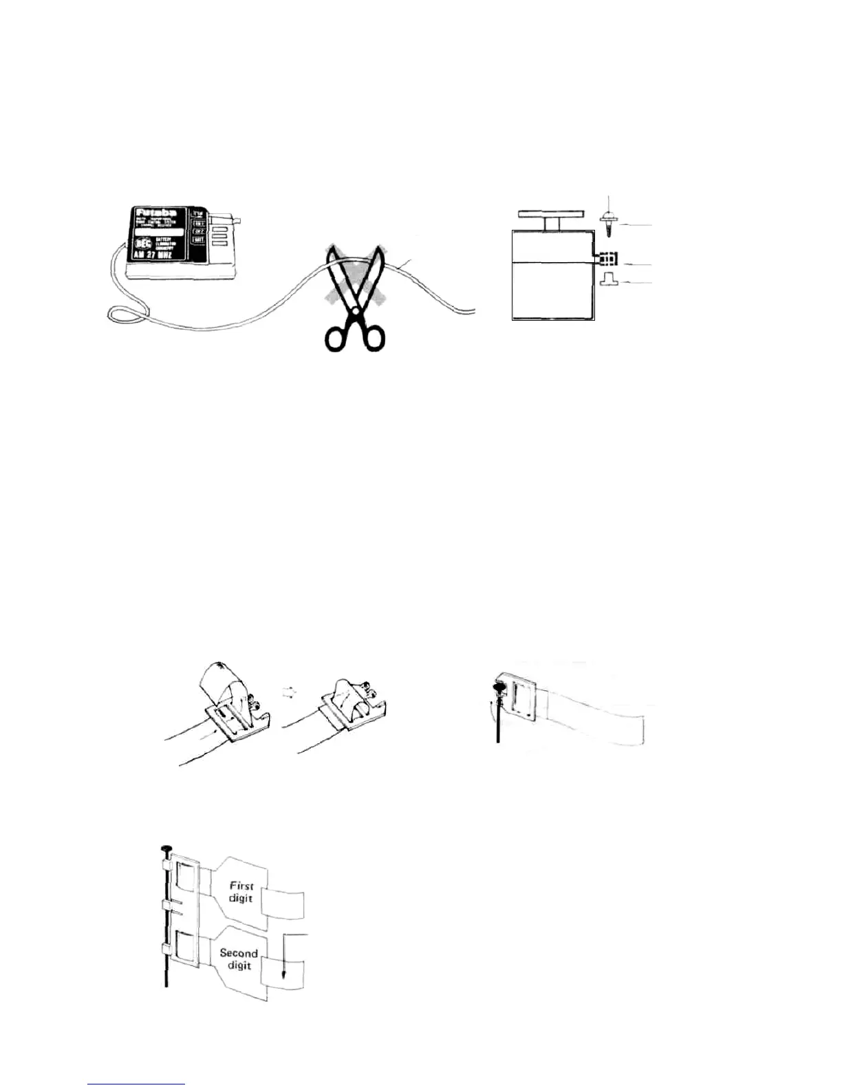
•Even
though the receiver antenna
wire
is
long,
do
not
cut
or
bundle
it.
The
range
of
the
radiowaves
will
be shortened.
Receiver antenna
wire
Wood screw
Rubber bushing
Grommet
Install
the
servos
firmly.
Install
the servo to the servo tray as
shown in the figure. In other
cases, install the servo as des-
cribed in the model manufac-
turer's manual.
R102GF
Scissors
• A spare horn is provided. Use it as required.
•Wrap
the receiver
in
sponge
rubber and
wrap
rubber
bands
around
the
sponge
rubber.
Mount the
receiver
so
it
is
not exposed to vibration, does not touch the frame, and does not move.
•When
the
receiver
is
installed on
a
board or
used
where
it
may
be
splashed
with
mud
and
water,
place
it
in
a
plastic
bag, etc. and wrap a rubber band around the open end of the bag to waterproof and dustproof the receiver. After use,
remove the receiver from the bag to prevent condensation.
• Use the rubber bands wrapped around the receiver to hold the servo and switch leads.
•After mounting is complete, recheck each part, then check the transmitting range by making the transmitter antenna
as short as possible and extending the receiver antenna fully and operating the set from a distance of 20m to 30m. The
movement of each servo should follow the movement of the transmitter sticks.
• The crystal can be changed from the outside of the receiver case. Always use a Futaba transmitter and receiver crystal
pair as the replacement crystals.
•USING THE FREQUENCY FLAG
Insert the frequency flag
into the flag holder as
shown here.
72/75MHZ Flag
Staple or glue with cyano-
acrylate ribbon here.
The flag can be attached to
and removed from the end
of the antenna with one
touch.
• The hook is for the optional neck strap. It is convenient when hanging the transmitter from your neck.
7