INSTRUCTION MANUAL
F-14
the blind cover from the well by undoing the two screws. The
switch can then be fitted in the desired location from the inside,
and the retaining nut fitted on the outside.
You will need to break out the switch position carefully from
the blind cover using a pair of tweezers or pointed-nose pliers
before screwing the cover in place again.
2. Multi-Prop module
Fitting this option module for auxiliary functions converts one of
the F-14 transmitter’s proportional channels 8 servo channels.
Mechanical installation of the module simply could not be ea-
sier: first remove the cover plate as described earlier, insert it
directly into one option well from the rear, then secure it with
the nuts supplied. Locate the 3-core cable attached to the mo-
dule and connect it to the pin row marked „Multi-Out“ on the
main transmitter circuit board. Connect the single-core wire to
the pin row marked „Multi-In“ 1, 2 or 3.
„Multi-In“ socket 1 2 3
Corresponding receiver output 8 7 6
Do not connect any other transmitter control to the channel you
have chosen to use!
The last stage is to re-fit the cover plate after opening up all
the holes required. Fig. 19 clearly shows how the module is
connected to the main transmitter circuit board.
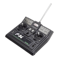
The module features a large number of switches which could
easily be confusing, so we strongly recommend that you write
a reminder of each one’s purpose on the marker labels, and
apply them to the module. Fig. 20 shows how this is done.
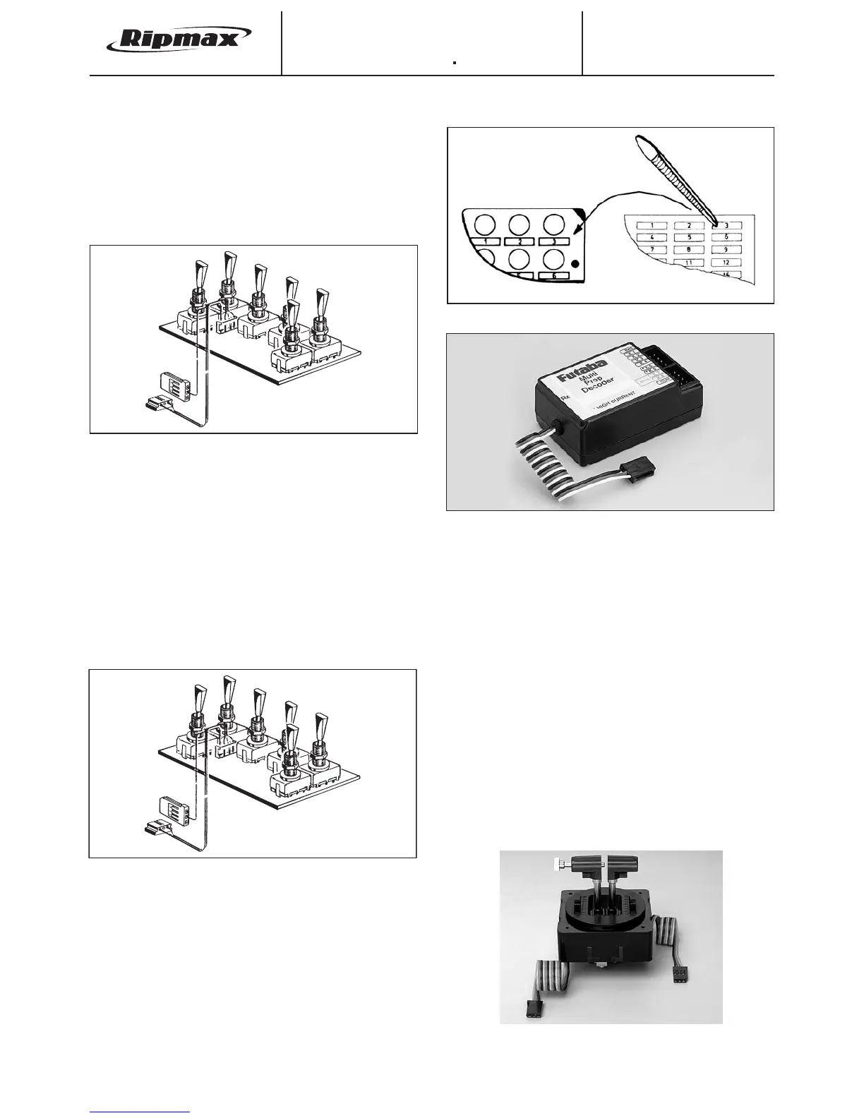
The module can only be used if the corresponding decoder is
used at the receiving end of the system. The correct decoder is
the Multi-Prop decoder which is shown in Fig. 21.
The decoder input must be connected to the receiver output
corresponding to the channel to which the Multi-Prop module is
connected in the transmitter. Eight servos can be connected to
the proportional outputs. For more details of the system please
refer to the operating instructions supplied with the Multi-Prop
decoder.
3. Multi-Switch 8 module
This module converts one proportional channel at the trans-
mitter into 8 switched functions for auxiliary working systems in
the model. The module features two 3-position switches, 3 On/
Off switches and 1 momentary switch, and this is sufficient to
cope with many applications. Mechanical installation of the mo-
dule is identical to that of the Multi-Switch-Prop 12 + 2 module.
The module can only be used if the corresponding decoder is
used at the receiving end of the system. The correct decoder
for this module is the Multi-Switch-8 decoder. Connecting the
decoder to the receiver and using the decoder are as descri-
bed for the Multi-Prop decoder.
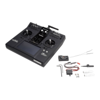
4. Navy Twin Stick (included in F-14 Navy)
The Navy Twin Stick is shown in Fig. 22; it is a special-purpo-
se parallel stick unit designed for true-scale control of model
boats equipped with a twin-motor power system. It can also be
used for separate control of mainsail and jib on model boats.
The stick functions are of the ratchet (non-centring) type with a
centre detent, and have individual superfine trims.
9
Fig. 18
Fig. 21
Fig. 20
Fig. 22
Fig. 19
Multi Out
Multi In 1, 2
or 3