EasyManua.ls Logo

FUTABA GY240 - User Manual

FUTABA GY240
2 pages
Print Icon
To Next Page IconTo Next Page
Loading...
FEATURES
No part of this manual may be reproduced in any form without prior permission.
The contents of this manual are subject to change without prior notice.
This manual has been carefully written. Please write to Futaba if you feel that any correc-
tions or clarifications should be made.
Thank you for buying a GY240 AVCS gyro.
Before using your new gyro, please read this manual thoroughly and use
the gyro properly and safely. After reading this manual, store it in a safe
place.
FOREWORD1
2
Adoption of AVCS
Since rudder trim changes caused by changes in tail
reaction torque changes due to wind and other meteorologi-
cal changes and main rotor rotation variations are automati-
cally cancelled, tail (rudder) operation is easy, making it
perfect for beginners.
SMM gyro sensor
Use of a new extremely small drift SMM (Silicon Micro
Machine) gyro sensor virtually eliminates rudder trim
changes during flight.
SET CONTENTS3
The GY240 comes with the following accessories:
4FUNCTIONS AND CONNECTIONS
GY240
Mini screwdriver (for adjustments)
Gyro sensitivity trimmer (GAIN)
Gyro sensitivity setting trimmer. Set to the maximum value at which the tail
does not hunt (minute vibration).
AVCS on/off switch (AVCS)
Turns the AVCS function on and off. In the "off" position, the GY240
operates as a conventional gyro.
Gyro direction switch (DIR)
Switches the gyro control direction. Must be switched according to the main
rotor rotating direction and rudder linkage direction.
(If you try to fly a helicopter with a clockwise rotation rotor with the gyro in
the reverse direction, the nose will swing to the left.)
Rudder servo connector
Connects the rudder servo.
Rudder input connector
Connects to the receiver rudder channel (ch4) output connector.
Rudder servo
Ratings
(Integrated sensor type AVCS rate gyro)
Control system: Digital advanced PI (Proportional Integration) control
Gyro sensor: SMM (Silicon Micro Machine) system vibration gyro
Operating voltage: +4 to +6VDC
Operating temperature range: -10˚C to +45˚C
Dimensions: 27 x 27 x 20mm
Weight: 25g (including connector)
Functions: Sensitivity trimmer, gyro operating direction adjustment switch,
AVCS on/off switch
High-speed, high-precision control
High-speed, high-precision control realized by digital
advanced control by microcomputer.
Small, light weight, integrated type
Small size (27 x 27 x 20mm) and light weight (25g) are
realized through high precision mounting technology.
Conductive resin case
Conductive resin case improves anti-EMI (static electricity,
radiowave interference) characteristic.
AVCS Gyro
Conventional gyros send control signals to the rudder servo
only when the tail of the helicopter moves. When the tail
stops moving, the control signal from the gyro becomes
zero. Conversely, the AVCS gyro continues to send control
signals to the servo even when the tail of the helicopter
stops moving.
The following sequentially describes the conventional gyro
and the AVCS gyro.
The GY240 is a high performance, small, and light weight
AVCS (Angular Vector Control System) gyro developed
for model helicopters.
Because the sensor section and control circuit are inte-
grated, mounting is easy.
helicopter to drift. When the tail drifts, the gyro generates a
control signal that stops the drift. When the tail stops
drifting, the control signal from the gyro becomes zero. If
the cross-wind continues to cause the tail to drift in this
state, the "stop" operation is repeated until the tail faces
downwind. This is called the "weathervane" effect.
Conversely, with an AVCS gyro, when the helicopter
encounters a cross-wind and the tail drifts, a control signal
from the gyro stops the drift. At the same time, the gyro
computes the drift angle and constantly outputs a control
signal that resists the cross-wind. Therefore, drifting of the
tail can be stopped even if the cross-wind continues to
effect the helicopter. In other words, the gyro itself auto-
matically corrects (auto trim) changes in helicopter tail trim
by cross-wind.
Considering operation of an AVCS gyro, when the tail of
the helicopter rotates, the servo also rotates in accordance
with the angle of rotation of the tail. When the tail stops
rotating, the servo judges that it has stopped in that posi-
tion. This is the auto trim function.
1M23N07402
Special Markings
Pay special attention to the safety at the parts of this manual that are indicated by the following marks.
Basic operation is described by considering the case when
the helicopter is hovering under cross-wind conditions.
With a conventional gyro, when the helicopter encounters a
cross-wind, the force of the cross-wind causes the tail of the
Mark Meaning
Procedures which may lead to a dangerous condition and cause death or serious injury to the
user if not carried out properly.
Procedures which may lead to a dangerous condition or cause death or serious injury to the
user if not carried out properly, or procedures where the probability of superficial injury or
physical damage is high.
Procedures where the possibility of serious injury to the user is small, but there is a danger of
injury, or physical damage, if not carried out properly.
Symbol: ; Prohibited ; Mandatory
Double-sided tape (3 sheets)
Operation of Conventional Gyro
Operation of AVCS Gyro
Question and Answer IconNeed help?

Do you have a question about the FUTABA GY240 and is the answer not in the manual?

Summary

Foreword and Product Overview

AVCS Gyro Explained

Explains the concept of AVCS gyros and their operation.

Conventional vs. AVCS Gyro Operation

Compares gyro operation under cross-wind conditions.

Key Features and Set Contents

Adoption of AVCS Technology

Benefits of AVCS for beginners and ease of use.

High-Speed, Precision Control

Realized by digital advanced PI control.

Compact and Lightweight Design

Small size and weight from high precision mounting.

SMM Gyro Sensor

Virtually eliminates rudder trim changes.

Conductive Resin Case

Improves anti-EMI characteristics.

Included Accessories

Lists mini screwdriver and double-sided tape.

Functions and Connections

AVCS On;Off Switch

Controls AVCS function for conventional gyro mode.

Gyro Direction Switch

Switches gyro control direction based on rotor rotation.

Gyro Sensitivity Trimmer

Adjusts gyro sensitivity to prevent hunting.

Connection Ports

Rudder input and servo connectors.

Usage and Adjustments

Mounting to Fuselage

Step-by-step guide for installing the GY240 unit.

Flying Adjustment (Conventional Mode)

Adjusts rudder neutral position with AVCS off.

Flying Adjustment (AVCS Mode)

Adjusts gyro sensitivity in AVCS mode.

Setting Precautions

Important notes on mounting the gyro sensor.

Fuselage Maintenance Precautions

Notes on maintaining fuselage rigidity for performance.

Operating Precautions

Key safety and operational advice for using the gyro.

Overview

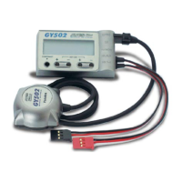
The Futaba GY240 AVCS Rate Gyro is a high-performance, compact, and lightweight angular vector control system (AVCS) gyro designed for model helicopters. Its integrated sensor section and control circuit simplify mounting.

Function Description

AVCS Gyro Operation: The GY240 operates in two modes: conventional gyro mode and AVCS mode.

In conventional gyro mode, the gyro sends control signals to the rudder servo only when the helicopter's tail moves. When the tail stops moving, the control signal from the gyro becomes zero. This can lead to the "weathervane" effect, where the tail drifts downwind under cross-wind conditions, requiring repeated "stop" operations until the tail faces downwind.

In AVCS mode, the GY240 continuously sends control signals to the servo even when the helicopter's tail stops moving. When the helicopter encounters a cross-wind and the tail drifts, the gyro first stops the drift. Simultaneously, it computes the drift angle and continuously outputs a control signal to counteract the cross-wind. This allows the tail drift to be stopped even if the cross-wind persists. Essentially, the gyro automatically corrects (auto trim) changes in helicopter tail trim caused by cross-wind. When the helicopter's tail rotates, the servo rotates in accordance with the tail's rotation angle. When the tail stops rotating, the servo judges that it has stopped in that position, which is the auto trim function.

Key Features:

  • AVCS Adoption: The AVCS system automatically cancels rudder trim changes caused by variations in tail reaction torque, wind, other meteorological changes, and main rotor rotation. This simplifies tail (rudder) operation, making it suitable for beginners.
  • SMM Gyro Sensor: The GY240 utilizes a new, extremely small drift SMM (Silicon Micro Machine) gyro sensor, which virtually eliminates rudder trim changes during flight.
  • High-Speed, High-Precision Control: Digital advanced control by a microcomputer ensures high-speed and high-precision control.
  • Small, Lightweight, Integrated Type: The compact size and light weight are achieved through high-precision mounting technology.
  • Conductive Resin Case: The conductive resin case improves anti-EMI (static electricity, radio wave interference) characteristics.

Functions and Connections:

  • AVCS On/Off Switch (AVCS): This switch turns the AVCS function on or off. In the "off" position, the GY240 operates as a conventional gyro.
  • Gyro Direction Switch (DIR): This switch adjusts the gyro control direction. It must be set according to the main rotor rotating direction and rudder linkage direction. Incorrect setting (e.g., flying a helicopter with a clockwise rotation rotor with the gyro in reverse direction) will cause the nose to swing.
  • Gyro Sensitivity Trimmer (GAIN): This trimmer adjusts the gyro sensitivity. It should be set to the maximum value at which the tail does not "hunt" (exhibit minute vibration).
  • Rudder Input Connector: Connects to the receiver's rudder channel (ch4) output connector.
  • Rudder Servo Connector: Connects to the rudder servo.

Usage Features

Mounting to Fuselage:

  1. Set the AVCS on/off switch to "off" by pushing the white protruding part of the switch downwards.
  2. Mount the GY240 body to the helicopter gyro bed using the supplied double-sided sponge tape. Ensure the bottom of the gyro body is perpendicular to the main rotor shaft (parallel to the tail pipe). For motor helicopters, install the GY240 at least 10cm away from the drive motor to avoid electromagnetic noise interference.
  3. Connect the GY240 rudder servo connector to the rudder servo.
  4. Connect the GY240 rudder input connector to the receiver rudder channel (ch4).
  5. Install the rudder servo and tail control wire linkage and servo horn according to the helicopter's instruction manual. For optimal performance, the servo horn and control wire should be perpendicular at the rudder neutral position.
  6. Check the rudder servo's direction of operation by moving the rudder stick. If it moves in the opposite direction, use the transmitter reverse function to reverse it.
  7. Set the gyro sensitivity trimmer to approximately 75% by turning it fully clockwise (100% position) and then adjusting to 75%.
  8. Check the gyro direction: if the rudder servo moves left when the helicopter's nose turns right, the gyro direction is correct. If it moves in the opposite direction, switch the gyro direction switch.

Flying Adjustment: In AVCS mode, the gyro automatically sets the rudder neutral position, making it difficult to judge the mechanical rudder neutral position. Therefore, for initial flight and linkage correction, turn off the AVCS function and adjust the mechanical rudder neutral position first.

Rudder Neutral Adjustment (with AVCS off):

  1. Set the AVCS on/off switch to "off."
  2. Set transmitter revolution mixing (pitch to rudder) to 0% or "off."
  3. Turn on transmitter power, then gyro power. Do not move the helicopter for approximately three seconds during initialization.
  4. Lift off and hover, then adjust the rudder neutral position with the transmitter trim lever. For large deviations, use the fuselage linkage to adjust the rudder neutral position.
  5. Adjust the gyro sensitivity to just before the helicopter tail starts to hunt.

AVCS Adjustment:

  1. Turn off the gyro power and turn on the AVCS on/off switch.
  2. With the transmitter power on, turn on the gyro power. Hold the transmitter rudder stick in the neutral position and do not move the helicopter for approximately three seconds.
  3. Hover the helicopter and adjust the gyro sensitivity to just before the helicopter begins to hunt.
  4. Adjust the rudder effect with the transmitter rudder adjustment functions (ATV, AFR, D/R, etc.).

Rudder Neutral Adjustment (in AVCS mode): In AVCS mode, the servo does not return to the neutral position even when the rudder stick is returned to neutral. To check the servo neutral position during linkage neutral check, set the AVCS switch to "off," or move the rudder stick at least three times left and right in one-second intervals and immediately return the stick to neutral. This operation resets the AVCS function and outputs the neutral signal to the servo.

Maintenance Features

Fuselage Maintenance Precautions:

  • Always perform proper maintenance for ultimate performance.
  • The rigidity of the fuselage tail significantly affects gyro performance.
  • Make the fuselage vibration as small as possible, as vibration adversely affects gyro operation.

Setting Precautions:

  • Always use the attached sensor tape to mount the gyro sensor. Reinstall the tape if it starts to separate or tear.
  • When mounting the GY240, leave a small margin so that the gyro connection cable is not stretched tight. A stretched cable can lead to malfunction and is dangerous.
  • For motor helicopters, mount the GY240 at least 10cm away from the drive motor to prevent interference from strong electromagnetic noise.
  • Mount the GY240 so that metal and other conductive parts do not touch its case. The conductive resin case helps reduce static electricity and electromagnetic interference, but its conductive surface can cause a short circuit if it touches other conductive parts.
  • Insert connectors fully and firmly. Loose connectors due to vibration can cause the helicopter to crash.

Operating Precautions:

  • Do not move the helicopter or the transmitter rudder stick from the neutral position for about 3 seconds during initialization when turning on the gyro power.
  • Never use the transmitter rudder trim in the AVCS mode. Operating the rudder trim during flight will change the neutral position, as the GY240 judges the rudder stick to be in the neutral position when power is turned on.
  • Avoid sudden temperature changes. Sudden temperature changes can cause the neutral position to change. For example, in winter, do not fly immediately after removing the model from a heated car; in summer, do not fly immediately after removing it from an air-conditioned car. Allow the model to stand for about 10 minutes for the gyro's internal temperature to stabilize before turning on power. Also, protect the gyro from direct sunlight or engine heat.
  • When using the GY240 in AVCS mode, set revolution mixing to OFF (or 0%).
  • Check the remaining receiver and gyro/servo NiCd battery operating time during adjustment and plan flights accordingly.

FUTABA GY240 Specifications

General IconGeneral
CategoryToy
TypeGyro
Operating Voltage4.8V - 6.0V
SensitivityAdjustable
Weight20 g

Related product manuals