Do you have a question about the FUTABA GV-1 and is the answer not in the manual?
Explains symbols used in the manual for warnings and cautions.
Important safety guidelines for initial governor setup.
Defines graphic symbols for required and prohibited operations.
Essential safety measures to observe during governor operation.
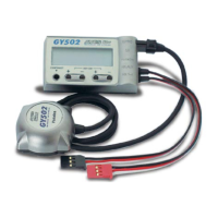
Lists all items supplied with the GV-1 governor package for checking.
Identifies and explains the different parts of the GV-1 control amplifier.
Explains how the GV-1 governor operates and how it's turned on/off.
Provides examples of GV-1 function selection based on transmitter usage.
Details on how to install the magnetic sensor and magnet onto the engine.
Procedure to check the correct mounting orientation of the magnet relative to the sensor.
Steps for physically mounting the sensor onto the helicopter.
How to adjust the sensor position for optimal signal output.
Wiring diagram and explanation for connecting the GV-1 to servos and receiver.
Important precautions for servo linkage and fuselage setup.
How to mitigate vibration issues affecting governor performance.
Considerations for using tuned silencers with the governor.
Recommendations for mounting the GV-1 control amplifier unit.
Explanation of the LCD panel and the keys used for setting functions.
Describes the low battery warning indicator and action to take.
A flowchart showing how to navigate through the GV-1's various functions.
Essential initial setup procedure for the governor to function correctly.
Setting the idle, high, and stop points for the throttle control.
How to input the rotor gear ratio for accurate speed measurement.
How to set target rotor speeds using the control amp.
Details on setting specific rotor speeds for different flight conditions.
How to configure the governor's ON/OFF control via switch or stick.
Configuring governor ON/OFF using the throttle stick.
How to set up the battery fail safe function for safety.
Activating and inhibiting the battery fail safe function.
Setting the throttle position for battery fail safe mode.
Configuring fail safe settings on the transmitter side.
Verifying the sensor output signal for correct operation.
Detailed explanation of available GV-1 functions.
Monitoring engine or rotor speed in real-time.
Displays and memorizes the maximum engine or rotor speed achieved.
Switching between engine and rotor speed display modes.
Inputting the gear ratio for accurate rotor speed calculations.
Setting the direction of the ON/OFF switch for governor control.
Configuring governor ON/OFF based on throttle stick position.
Displays the current governor ON/OFF status and conditions.
Setting a high stick position to turn the governor off.
Displays the current battery voltage and low voltage warning.
Selecting the operation mode for the mixture servo.
Setting the mixture rate for each point of the curve.
Setting the throw for the mixture servo.
Reversing the direction of the mixture servo.
Adjusting the mixture servo trim using a vacant channel.
Activating and inhibiting the battery fail safe function.
Setting the throttle position for battery fail safe mode.
Sets the governor control range (idle/high/stop points).
Explains error messages and their causes during setup.
Tests the servo operation based on limit settings.
Monitors the rotation sensor signal level.
Technical specifications and ratings of the GV-1 governor.
Definitions of terms and symbols used in the manual.
A sheet for recording GV-1 parameter settings.
Instructions for requesting repair services for the product.