33
INSTALLATION AND ADJUSTMENT
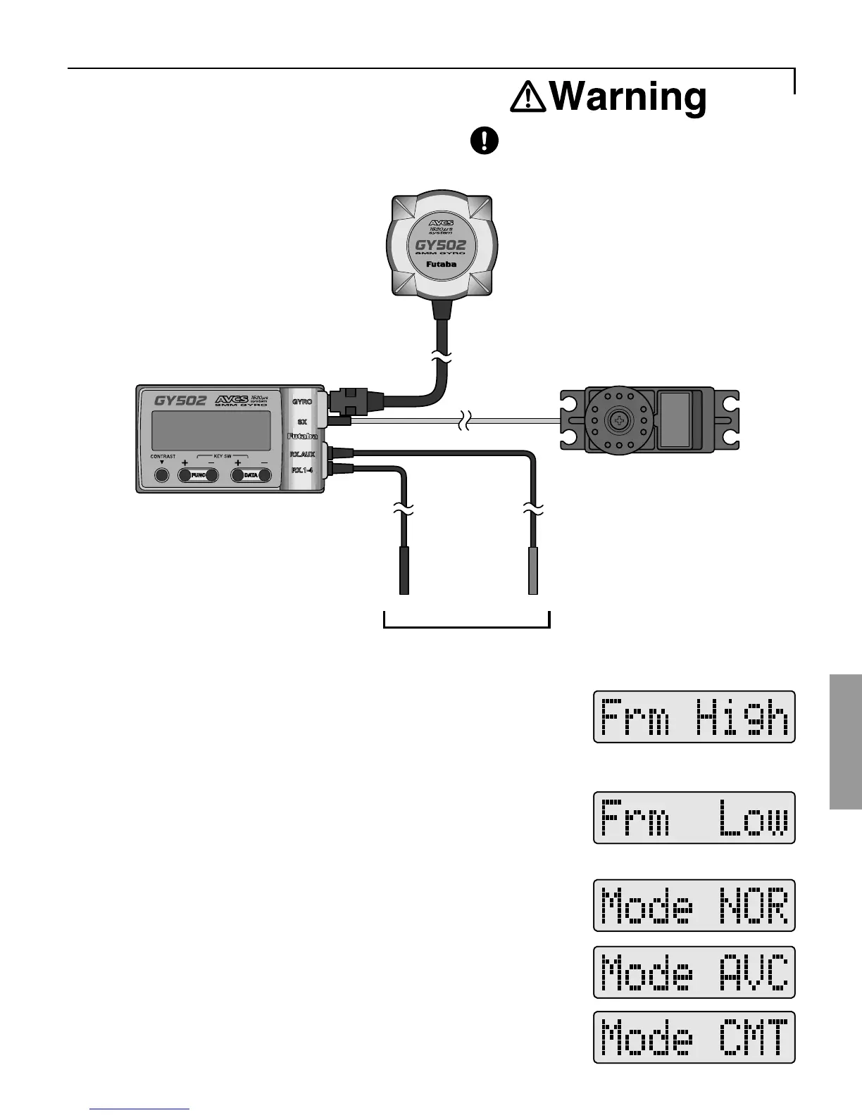
2 Connections
Connect the GY502, receiver
and servo as shown below.
Insert the connectors fully
and firmly.
If a connector works loose
due to vibration during flight,
control may be lost and result
in a dangerous situation.
•Connect the sensor to the
amp sensor input ("GYRO").
•Connect the rudder servo to
the amp servo output ("SX").
•Connect the amp rudder
input ("RX,1-4") input
connector to the receiver
rudder channel (ch4).
Black Red
•Connect the amp remote
gain input ("RX,AUX")
connector to the receiver
sensitivity setting channel
(normally ch5).
To receiver
3 Servo selection
When using a digital servo (S9253, S9250,
S9450, etc.) as the rudder servo, select High at
the Frm screen.
When using a servo other than a digital servo,
select Low at the Frm screen.
When using the gyro only in the NOR mode,
select NOR. When using the gyro only in the
AVCS mode. select AVCS. When using the
gyro in both the AVCS and NOR modes,
select CMT.
4 Gyro operation mode selection