FDC_C-Series_Quick_Operation_User_Manual_UMQOC621A.doc Page 14 of 20
5. PROGRAMMING:
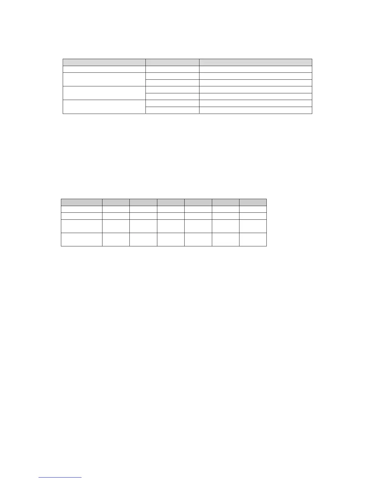
5.1 User Security: There are two parameters PASS (password) and CODE (security code) to control the data security function.
CODE Value PASS Value
ccess Ri
hts
0 Any Value All parameters are changeable
1000
=1000 All parameters are changeable
≠1000 Only user menu parameters changeable
9999
=9999
ll parameters are chan
eable
≠9999 Only SP1 to SP7 are changeable
Others
=CODE All parameters are changeable
≠CODE No parameters can be changed
5.2 Signal Input:
INPT: Select the sensor type or signal type for signal input.
Range: (Thermocouple) J_TC, K_TC, T_TC, E_TC, B_TC, R_TC, S_TC, N_TC, L_TC,
(RTD) PT.DN, PT.JS or (Linear) 4-20, 0-20, 0-60, 0-1V, 0-5V, 1-5V, 0-10
UNIT: Select the process unit.
Range: °C, °F, PU (Process unit). If the unit is neither °C nor °F, then select PU.
DP: Select the resolution of process value.
Range: For Thermocouple and RTD Signal NO.DP, 1-DP and for Linear Signal NO.DP, 1- DP, 2-DP, 3-DP.
INLO: Select the low scale value for the linear type input.
INHI: Select the high scale value for the linear type input.
5.3 Control Output: There are 4 kinds of control modes can be configured as shown below.
Control Mode OUT 1 OUT 2 O1HY O2HY CPB DB
Heat Only REVR X ∆ X X X
Cool Only DIRT X ∆ X X X
Heat PID
Cool ON-OFF
REVR DE.HI X O X X
Heat PID
Cool PID
REVR COOL X X O O
X: Not applicable O: Adjust to meet process Requirements ∆: Required if ON-OFF Control is configured
5.4 Alarm: The controller has up to four alarm outputs depending on the controller model. There are 11 types of alarm functions and
one dwell timer that can be selected. There are 4 kinds of alarm modes (A1MD, A2MD, A3MD, and A4MD) available for each alarm
function (A1FN, A2FN, A3FN, and A4FN). In addition to the alarm output, output 2 can also be configured as an alarm. But output 2
has only provides 8 different alarm functions or dwell timer available.
5.5 Alarm Modes: There are four types of alarm modes available for each alarm function.
Normal Alarm (ALMD = NORM): When a normal alarm is selected, the alarm output is de-energized in the non-alarm condition and
energized in an alarm condition.
Latching Alarm (ALMD = LTCH): If a latching alarm is selected, once the alarm output is energized, it will remain unchanged even if
the alarm condition is cleared. The latching alarm can be reset by pressing the RESET key once the alarm condition is
removed.
Holding Alarm (ALMD = HOLD): A holding alarm prevents an alarm condition during power up. This will ignore the alarm condition
at first time after power on. Afterwards, the alarm performs the same function as normal alarm.
Latching / Holding Alarm (ALMD = LT.HO): A latching / holding alarm performs both holding and latching functions. The latching
alarm is reset when the RESET key is pressed after the alarm condition is removed.
Set Point Holding Alarm (ALMD = SP.HO): A set point holding alarm prevents an alarm from power up and / or changing set point.
The alarm output is de-energized whenever the set point is changed even if it is in an alarm condition. The alarm reverts to a
normal alarm once the alarm condition is removed.
5.6 Alarm Delay: In certain applications during startup, nuisance alarms will be generated before the process value reaches the set
point. To avoid these kinds of nuisance alarms, a time delay for alarms is available. To enable the time delay for alarms, set the
delay time using the A1DL, A2DL, A3DL, and A4DL parameters. These parameters will avoid the nuisance alarm during the process
value reaches set point.
 Loading...