FDC_C-Series_Quick_Operation_User_Manual_UMQOC621A.doc Page 6 of 20
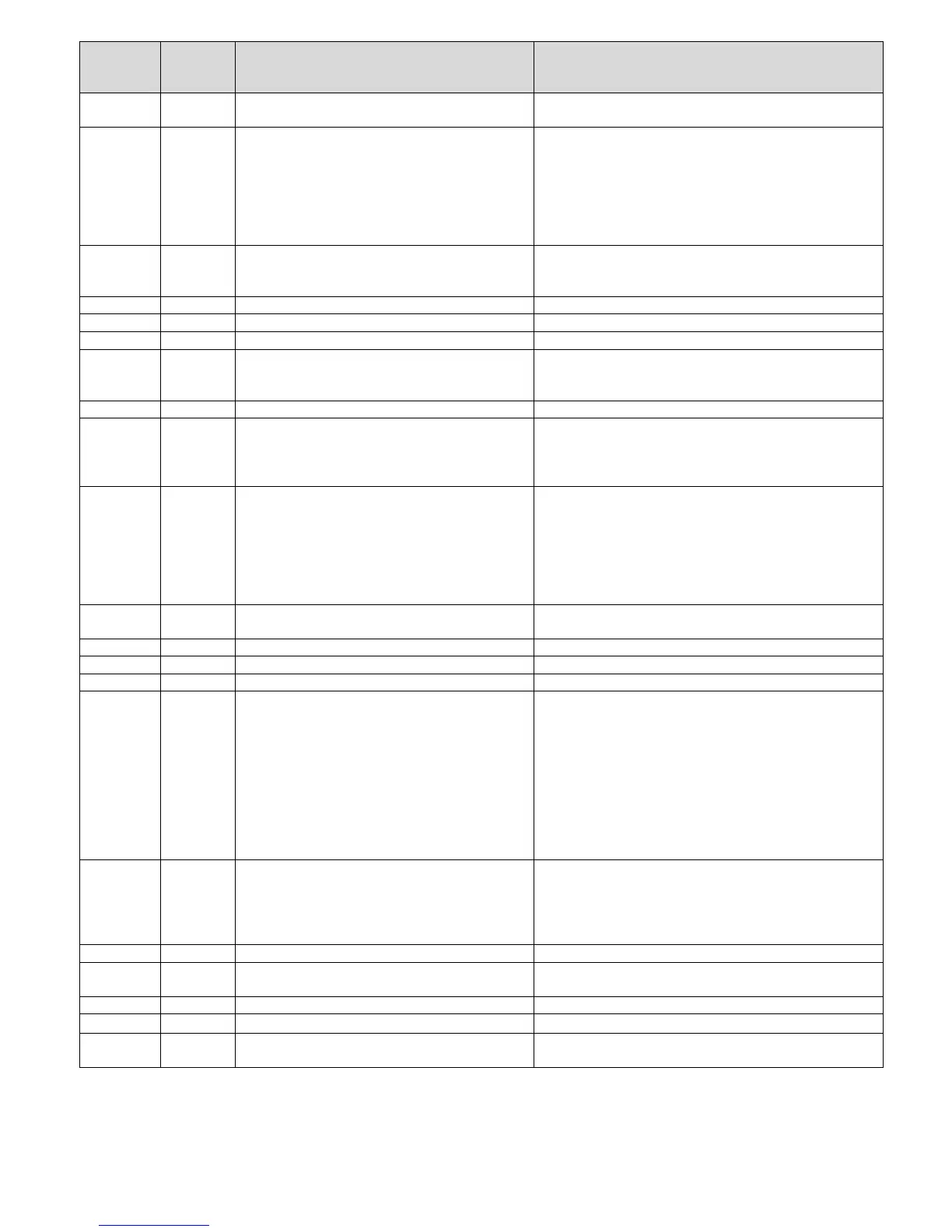
Modbus
Register
Address
Parameter
Notation
Parameter Description Range
20 OUT1 Output 1 function
REVR: Reverse (heating) control action
dIRt : Direct (cooling) control action
21 O1TY Output 1 signal type
RELY: Relay output
SSrd: Solid state relay drive output
4-20: 4-20mA linear current
0-20: 0-20mA linear current
0-5V: 0-5VDClinear voltage
1-5V: 1-5VDC linear voltage
0-10: 0-10VDC linear voltage
22 O1FT Output 1 failure transfer mode
Select BPLS
Bumpless transfer
, o
0.0 ~ 100.0 % to continue
output 1 control function if the sensor fails, or select OFF (0) or
ON (1) for ON-OFF control
23 O1HY Output 1 ON-OFF control hysteresis Low:0.1°C(0.2°F) High: 50.0°C(90.0°F)
24 CYC1 Output 1 cycle time Low: 0.1 High: 90.0 sec.
25 OFST Offset value for P control Low: 0 High: 100.0 %
26 RAMP Ramp function selection
NoNE: No Ramp Function
MINR: Use unit/minute as Ramp Rate
HRR: Use unit/hour as Ramp Rate
27 RR Ramp rate Low: 0.0 Hi
h: 500.0°C
900.0°F
28 OUT2 Output 2 function
NoNE:Output2 turned off
COOL: Cooling PID Function
AL1: Alarm 1 Function
rAL1:Reverse Alarm 1 Function
29 O2TY Output 2 signal type
RELY: Relay output
SSrd: Solid state relay drive output
4-20: 4-20mA linear current
0-20: 0-20mA linear current
0-5V: 0-5VDClinear voltage
1-5V: 1-5VDC linear voltage
0-10: 0-10VDC linear voltage
30 O2FT Output 2 failure transfer mode
Select BPLS (Bumpless transfer),or 0.0 ~ 100.0 % to continue
output 2 control function if the sensor fails
31 CYC2 Output 2 cycle time Low: 0.1 High: 90.0 sec.
32 CPB Coolin
proportional band value Low: 50 Hi
h: 300 %
33 DB Heatin
-coolin
dead band
ne
ative value= overlap
Low: - 36.0 Hi
h: 36.0 %
34 A1FN Alarm 1 function for alarm 1 output
NoNE: No alarm function
dtMR: Dwell timer action
dE.HI: Deviation high alarm
dE.Lo: Deviation low alarm
db.HI: Deviation band out of band alarm
db.Lo: Deviation band in band alarm
PV.HI: Process value high alarm
PV.Lo: Process value low alarm
H.bK: Heater break alarm
H.St: Heater short alarm
35 A1MD Alarm 1 operation mode
NoRM: Normal alarm action
LtCH: Latching alarm action
HoLd: Hold alarm action
Lt.Ho: Latching & Hold action
SP.Ho: Set point holding alarm
36 A1HY Hysteresis control of alarm 1 Low: 0.1°C High: 50.0°C(90.0°F)
37 A1FT Alarm 1 failure transfer mode
OFF: Alarm output OFF if sensor fails
ON: Alarm output ON if sensor fails
38 A1SP Alarm 1 set point Low: -19999 High: 45536
39 A1DV Alarm 1 deviation value Low: -19999 High: 45536
40 A2OT Alarm 2 Output
ALM: Alarm 2 output 1
RALM: Reverse Alarm 2 Output
 Loading...