12 of 13
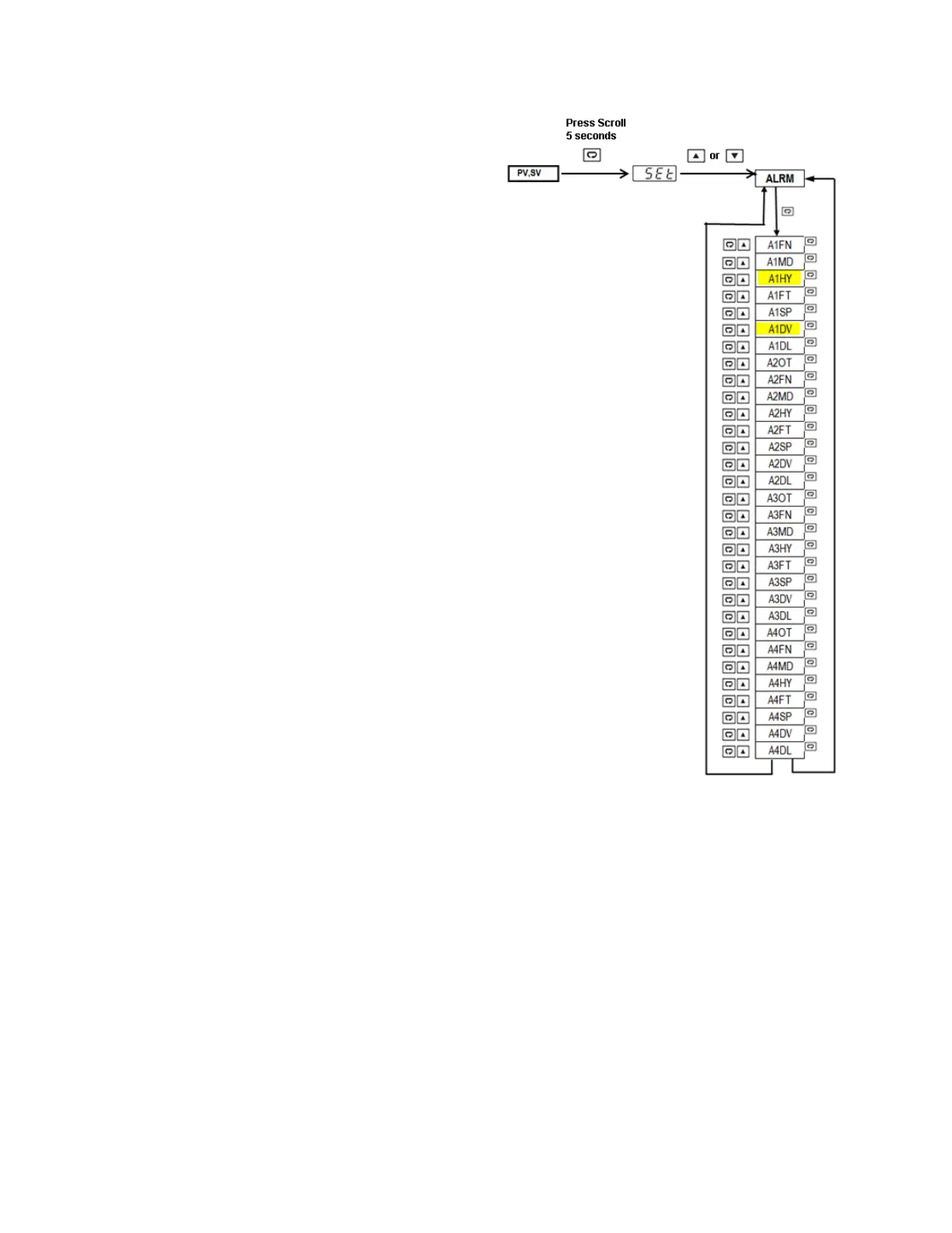
• Press and Hold scroll key for 5 seconds
to enter Setup menu (upper display will
show SET).
• Press up or down key repeatedly to
access alarm parameters (lower display
will show ALRM).
• Press scroll key to cycle through alarm
parameters and access alarm 1
hysteresis (upper display will show A1HY
and lower display will show current
value).
• Press up or down key to change
hysteresis value.
• Press scroll key to cycle through alarm
parameters and access alarm 1 deviation
set point (upper display will show A1DV
and lower display will show current
value).
• Press up or down key to change alarm
deviation value.
• Press reset key to exit menu and return
to normal PV/SV display.
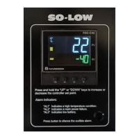
3.3 Power Status Alarm Indicators
The FDC-C42 events inputs 1 and 2 and alarm outputs 2 and 3 are pre-configured to act as power supply
status alarms. Event input 1 and alarm output 2 (AL2) are utilized to indicate a power failure. Under normal
operation, event input 1 will be activated indicating power is present. When main power is lost, event input
1 will deactivate, and in turn cause alarm 2 relay output to energize. When the alarm relay’s output is
energized, the alarm output status indicator (labeled AL2 on the front panel) will be illuminated.
Event input 2 and alarm output 2 (AL3) are utilized to indicate low battery. Under normal operation, event
input 2 will be deactivated. When the battery is low, event input 2 will be activated and in turn cause alarm
3 relay output to energize. When the alarm relay’s output is energized, the alarm output status indicator
(labeled AL3 on the front panel) will be illuminated.
 Loading...