12
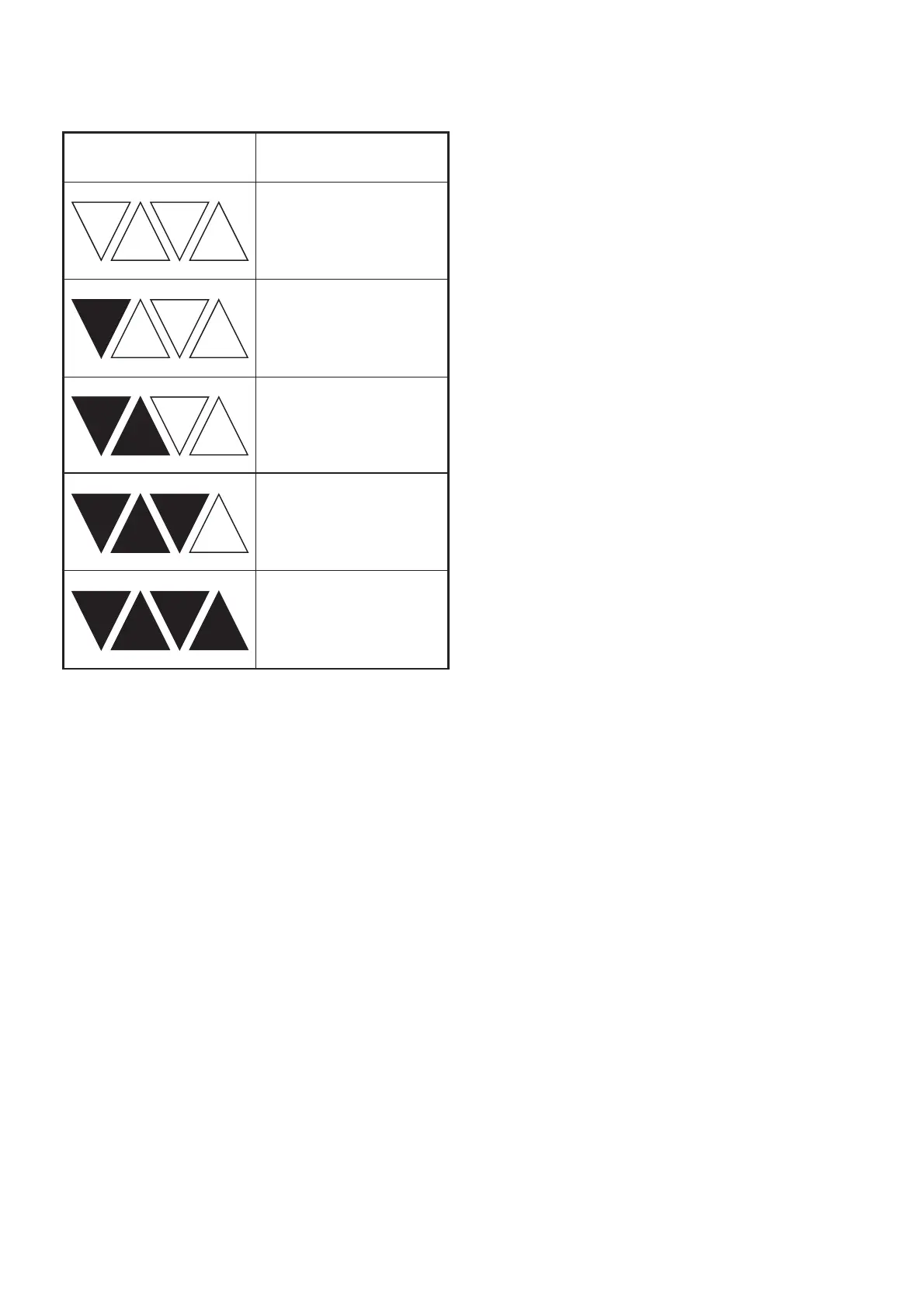
CHARGE STATUS
To display the amount of charge left in the battery,
press the charge level indicator button, Fig.2.
ASSEMBLY
INSTALLING THE LOWER HANDLE
To attach the lower handles, first remove the two
lower handle locking knobs. Place the lower handle in
position by aligning the 2 lower handle ends on the
outer side of the metal mounting plate nubs located at
the bottom of the mower deck, Fig.3. There are 3
different height mounting positions to suit the
operator, make sure both sides are installed in the
same position.
Once in position, insert the bolt on each side through
the mounting plate, Fig.4, and then through the lower
handle. Orientate the bolt so the head sits correctly in
the depression in the handle tube.
Once the bolts are loosely in position, attach the lower
handle locking knobs over the bolts and secure by
turning clockwise until tight, Fig.5.
INSTALLING THE UPPER HANDLE
To attach the upper handle, position the upper
handle and insert the lock bolt through the
matching holes at the bottom of the upper handle and
the top of the lower handle, Fig.6. Orientate the bolt
so the head sits correctly in the depression.
Once the bolt is loosely in position, attach the upper
handle locking knob over the bolt and
secure by turning clockwise until tight, Fig.7.
Secure the cable cord to the handle with the cable
holder, Fig.8.
To lower the handle assembly:
F
ully loosen the locking knobs on the sides of the
handle and fold the upper handle down.
Unscrew the lower handle locking knobs.
Fold the lower handle forward, making sure not to
bend or kink the control cables.
INSTALLING THE GRASS COLLECTION BOX
Remove key and battery pack if installed.
Lift the impact protector, Fig.9.
Lift the grass collection box by its handle and place
under the impact protector so that the hooks on the
grass collection box are seated into the slots on the
mower body, Fig.10.
Release the impact protector. When installed
correctly, the hooks on the grass collection box will
rest securely in the slots on the mower body.
INSTALLING AND REMOVING BATTERY PACK
Warning! Always remove the battery packs from your
tool when you are assembling parts, making
adjustments, cleaning, carrying, transporting or when
not in use. Removing the battery packs will prevent
accidental starting that could cause serious personal
injury.
Lift up the battery cover and slide a battery pack into
one of the slots until it clicks into place, Fig.11 & 12.
(Note the battery has raised ribs which allows it to fit
into the machine only one way). Repeat this procedure
for the second battery. If the machine is not going to
be used immediately, do not insert the key.
To remove the battery, remove the key, Fig.13, press
the battery release button, and pull the battery pack
out of the slot.
CONTROLS
DUAL-ACTION SWITCH (FIG.14)
The motor is controlled by a dual-action switch to
prevent accidental start ups.
Press the safety button (2) and pull the lever (1) to
start the machine.
WARNING! Starting up the motor will engage the
rotor at the same time.
The motor stops automatically when the lever (1) is
released.
OPERATION
STARTING/STOPPING THE MOTOR
To start the motor: Open the battery cover and insert
the key into the slot, Fig.15
Press and hold the safety lock-off button, Fig.16.
Charge level indicator Amount of charge
remaining
0-10%
10-25%
25-50%
50-75%
75-100%