3. Operation
3.1 Calibration
3.1.1 Based on System Sensitivity
Sincethemicrophonesignalisampliedby20dBintheGainandFilterUnitType26HT,the
nominal system sensitivity at the output of the Power Module corresponds to 0.8 V/Pa. In other
wordswhenthemeasuredoutputvoltagefromthePowerModuleis0.8VRMS,themicrophone
isbeingsubjectedto94dBre.20μPa.
Theactualsystemsensitivityisquotedontheindividualcalibrationchartsuppliedwitheach
Low-noise Microphone System Type 40HT.
Basedonthisinformation,proceedasfollows:
1. ConnecttheType40HTviaitsLEMOplugtotheLEMOinputsocketoftheType12HF
(see Fig. 1.3).
2. Connect via a suitable cable the BNC output of the Type 12HF (see Fig. 1.3) to the ana-
lyser to be used and switch both Power Module and analyser on.
3. Adjusttheanalysertoindicate94dBre.20μPaforanRMSinputofSvolts;whereS is the
systemsensitivityoftheType40HTasquotedonthecalibrationchart.
3.1.2 Pistonphone
APistonphoneType42AAttedwithaCouplerRA0090(bothavailablefromG.R.A.S.)canbe
usedtoproduce94dBre.20μPaonthemicrophoneoftheType40HT.
Note:aPistonphonettedwithanormal½-inchcouplercannotbeusedbecausethiswillover-
loadthesystemwithalevelof114dBre.20μPa.
Proceedasfollows:
1 ConnecttheType40HTviaitsLEMOplugtotheLEMOinputsocketoftheType12HF
(see Fig. 1.3).
2. Connect via a suitable cable the BNC output of the Type 12HF (see Fig. 1.3) to the ana-
lyser to be used and switch both Power Module and analyser on.
3. Unscrew and remove the normal coupler of the Pistonphone.
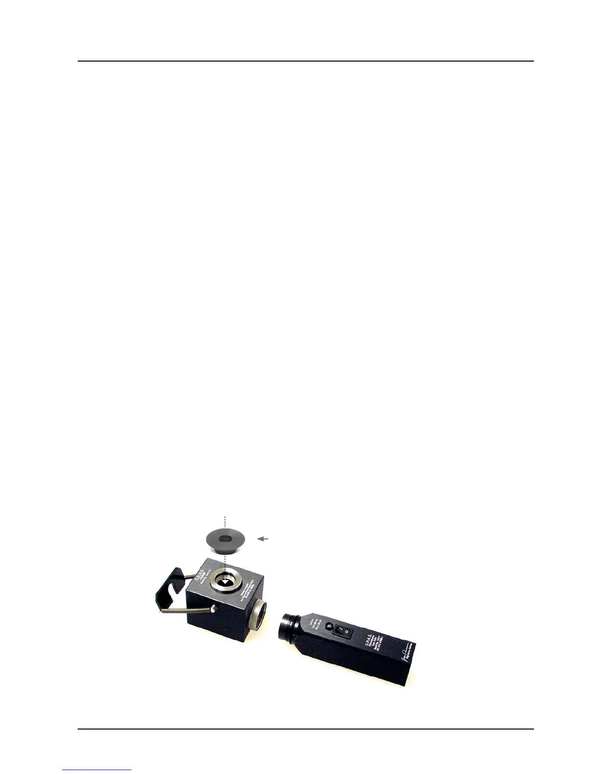
4. ScrewtheCouplerRA0090tothePistonphone,seeFig.3.1.
5. Pushtthe½-inchadapterGR0619shownFig.3.1totheentranceofthecouplerRA0090.
Fig. 3.1 Pistonphone without its normal coupler and ready to accept the
Coupler RA0090
GR0619
Adapter for ½-inch microphone
 Loading...