G.R.A.S. Sound & Vibration
Single-channel Low-noise Measuring System consisting of: Type 40HT and Type 12HF - Page 12
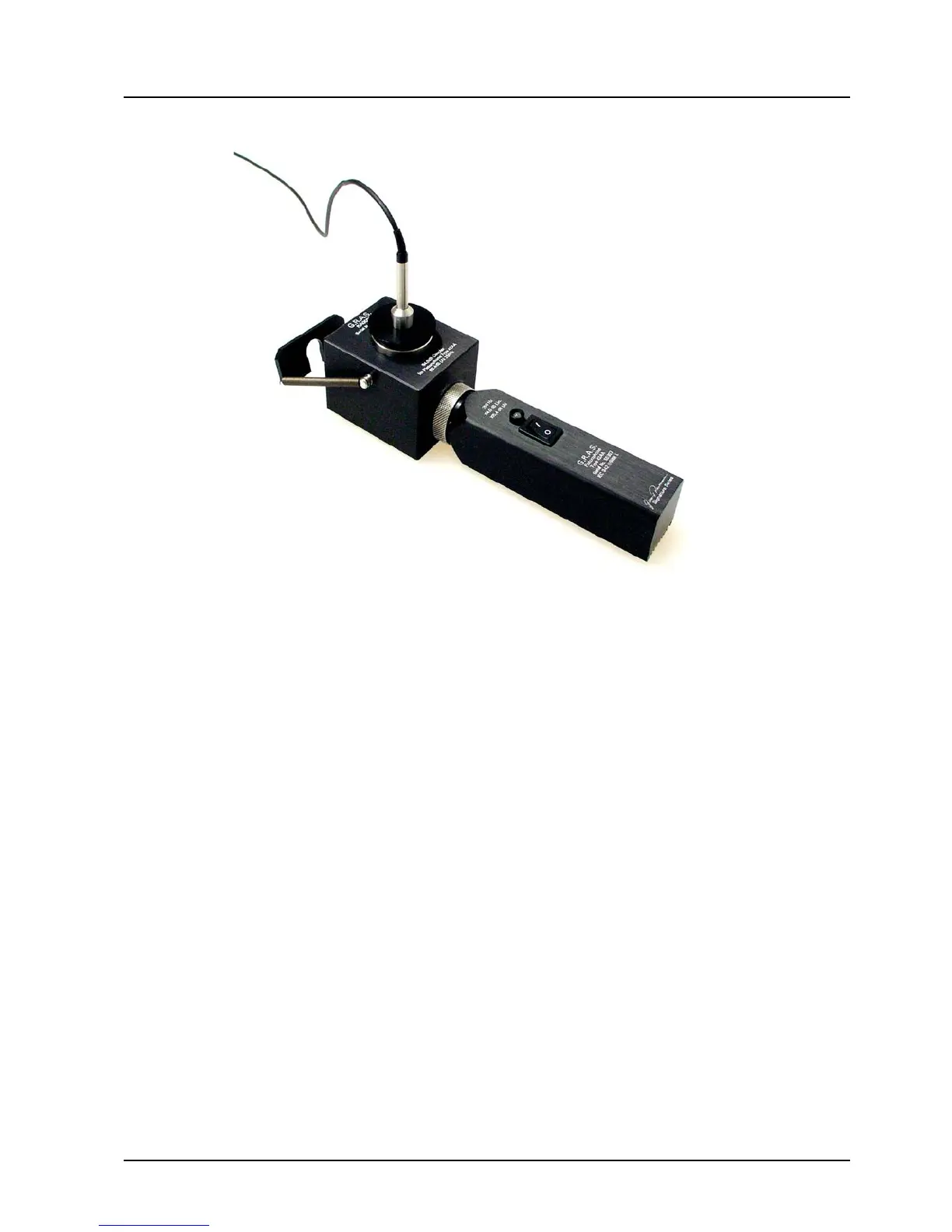
Fig. 3.2 Pistonphone tted with Coupler RA0090 and the microphone
inserted into the Coupler
6. Mount the microphone of the Type 40HT in the Coupler as shown in Fig. 3.2 and switch the
Pistonphone on.
7. Adjusttheanalysertoindicate94dB*re.20μPa.
3.2 Measurements
1. Assemble the system as shown in Fig. 1.3.
2. Connect the output from the Power Module to an analyser.
3. Switch both Power Module and analyser on.
4. Calibrate the set up via one of the methods described in section 3.1.
5. Select which microphone operation to use via the switch on the front panel of the Type
12HF marked Pressure / Free Field.
AtthispointyoucanmakeyourmeasurementsbutkeepaneyeontheoverloadwarningLEDs
to avoid overloading the system and invalidating the measurements.
* Plus any corrections for barometric pressure. See pistonphone manual.
 Loading...