G.R.A.S. Sound & Vibration
Single-channel Low-noise Measuring System consisting of: Type 40HT and Type 12HF - Page 9
• 7-pinLEMOEGA3071BinputsocketfortheLEMOplugonthecableoftheGainand
Filter Unit Type 26HT. Wiring diagram shown in Fig. 2.2.
• BNCoutputsocketfortheselected(Pressure / Free Field) output signal.
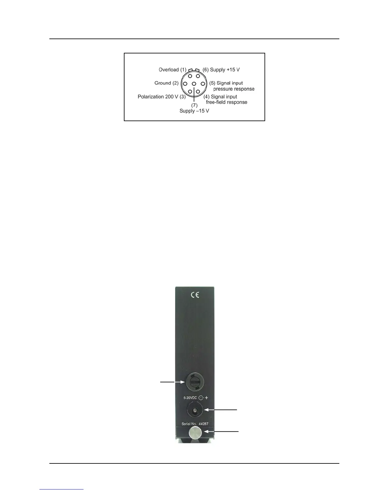
2.2 Rear Panel
The rear panel has the following features (see Fig. 2.3)
• Twist/releaseholderfor315mAfast-blowfuse.
• Inputsocketforanexternalvoltagesupplyof6V-20VDC;centrepin+terminal.Usethe
Mains/line Adapter AB0010 supplied with the Type 12HF.
• Lockingscrew
Unscrew to remove base plate and gain access to the battery pack (see section 2.3).
 Loading...