ATTUATORI .
- PNEUMATIC ACTUATORS AND ACCESSORIES -
UsermanING ISSUE .10 March 2004
GT ATTUATORI S.r.l. REA MI 1558400 FAX (02) 90390368
V.le Europa 17 - 20090 Cusago Partita IVA e Cod.Fisc.12449540157 TEL (02) 90390322
Milan - ITALY- E-mail g.trevisan@iol.it
www.gtrevisan.it
PAG. 3 OF 20
INSTALLATION
OPERATION &
MAINTENANCE MANUAL
1.0 INTRODUCTION
G.T. Attuatori offers a largest ranges of pneumatic rack and pinion actuators . Conceived for the installation on
valves of control of the fluids, which ball valves, butterfly valves, etc.and have fed with pressed air.
The actuarors are built for operate with a maximum pressure of 10 Bar., and tested for an operational least life
of 1 million of manoeuvres.
The greasing performed during the assemblage guarantees a correct lubrication of the actuators for at least
500.000 manoeuvres.
actuators are designed to operate within the pressure range of 1.4 Bar (20 PSIG) to 10 Bar (142 PSIG)
and are offered in two styles:
- DOUBLE ACTING: Available with rotation of 90°, 120° e 180° .
- SPRING RETURN: Available with rotation of 90°.
The double acting and spring return actuators can easily be field converted to the other configuration by
insertion or removal of the unique patented G.T. Attuatori spring cartridges.
2.0 STORAGE
All G.T. Attuatori actuators are factory lubricated for life.
The actuator ports are plugged to prevent liquids or other materials from entering the actuator during shipment.
If the actuators are to be stored for a long period of time before installation, the units should be stroked
periodically to prevent the seals from setting. (Note: the plugs must be removed in order to stroke actuators).
Storage should be indoors and the units should be protected against humidity and other harmful elements.
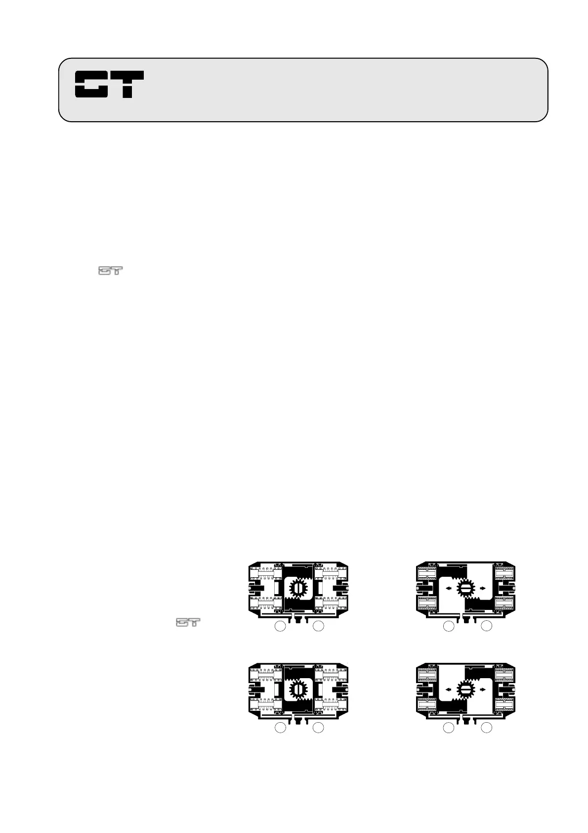
FIGURES
1A - 1B - 1C - 1D
Cut away top views of
spring return actuators, for
Fail Clock-Wise applications
Assembling type A (fig.1A),
and Fail Counter Clock-wise
applications,Assembling
type C (fig.1C).
A B A B
Figure 1A (Closed position) Figure 1B (Open position)
A B A B
Figure 1C (Closed position) Figure 1D (Open position)
Assembling type C = Fail Counter Clock-Wise application
Assembling type A = Fail Clock-wise application
 Loading...