Information in this document can be modified without notice.
Edition 07.2020 ..
03
5
Door Multipoint Locking System
Solid brass handle & 45mm plate series
Assembly and Operating Instructions
A-opener, SECUREconnect , Fingerprint Scanner or Code Keypad
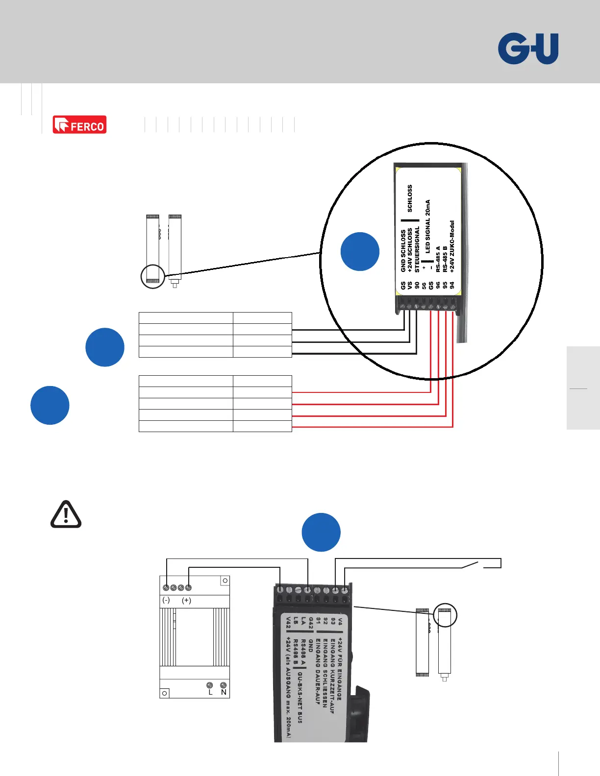
– Door Leaf Mounted Connection Diagram
Attention:
Only V DC voltage sources in accordance
with EN may be used.
Connecting cable Signal
GND (minus)
Grey (blue)
Brown 24 V (plus)
Black Control line
Connecting cable Signal
Yellow GND (minus)
White RS-485 A
Green RS-485 B
Brown 24 V (plus)
Stabilized power supply
V AC / V DC, .A
Switch control (optional)
Fingerprint
scanner or
code keypad
Cable routing of module (leaf-side)
Please use the enclosed system cable to connect the module.
The SECUREconnect and the access control module communicate
via an encoded bus.
Connection terminals of SECUREconnect R (frame-side)
The terminals V and G are provided for the connection of an external
V DC voltage supply to operate SECUREconnect .
SECUREconnect F
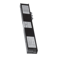
SECUREconnect R
GS
VS
GS
Door Multi-point Locking System Automatic Smart Access Controlled
A-opener
A
E
F
D