Do you have a question about the G-U BKS SecureConnect 200 and is the answer not in the manual?
Explains symbols like DANGER, WARNING, CAUTION, ATTENTION for hazard identification.
Covers electrical work hazards, wire sizing, and mains connection safety precautions.
Provides essential advice for safe operation, hazard prevention, and longevity.
Lists all components included in the SECUREconnect 200 delivery package.
Details suitable installation locations and intended use for SECUREconnect 200 components.
Lists supply voltage, protection type, operating temperature, and other device specifications.
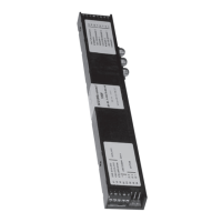
Visual representation of the SECUREconnect 200F and 200R connection layout.
Step-by-step guide for attaching faceplates to SECUREconnect 200 components.
Instructions for mounting the contact holder and its associated contact plates.
How to adjust the rebate clearance for the SECUREconnect 200F tappet contacts.
Guidance on installing SECUREconnect 200 units into various door types (timber, metal, PVC).
Best practices for wiring, electrical connections, and safety compliance.
Identification and purpose of terminals on the SECUREconnect 200 unit.
Specific terminals for monitoring contacts and other inputs on the door leaf component.
Terminals for power supply, bus communication, and control inputs on the frame component.
Steps for initial communication, pairing, and re-pairing SECUREconnect components.
Interpretation of LED lights on SECUREconnect 200R/200F for device status.
Operation modes like Short-time OPEN, Permanent OPEN, and Door Locking.
Lever handle engagement/disengagement for OPEN, locking, and closing operations.
Diagram illustrating the wiring for latchbolt status monitoring.
Connection diagram for integrating the Secury Automatic with an A-opener unit.
Detailed wiring diagram for Series 19 motor-driven locks using a 14-wire cable.
Wiring diagram for 'EK' lock series 19, including a 14-wire connecting cable.
Guidance on unit operation, part replacement, and contact cleaning.
Instructions for the correct disposal of the SECUREconnect 200 as electronic waste.
| Brand | G-U |
|---|---|
| Model | BKS SecureConnect 200 |
| Category | Door Opening System |
| Language | English |