Power and data transmission unit
Mounting und operating instructions
SECUREconnect 200
. | EE | Printed in Germany
EN
6. Wiring advice
6.1 Wiring and electrical connection
The cables must be laid in such a way that they cannot be squeezed in or
dammaged in the area of the lock forend during installation.
Distribution boxes must be accessible for maintenance work. Cable types,
lengths, and cross sections must conform to the specifications.
6.2 SECUREconnect 200 terminals
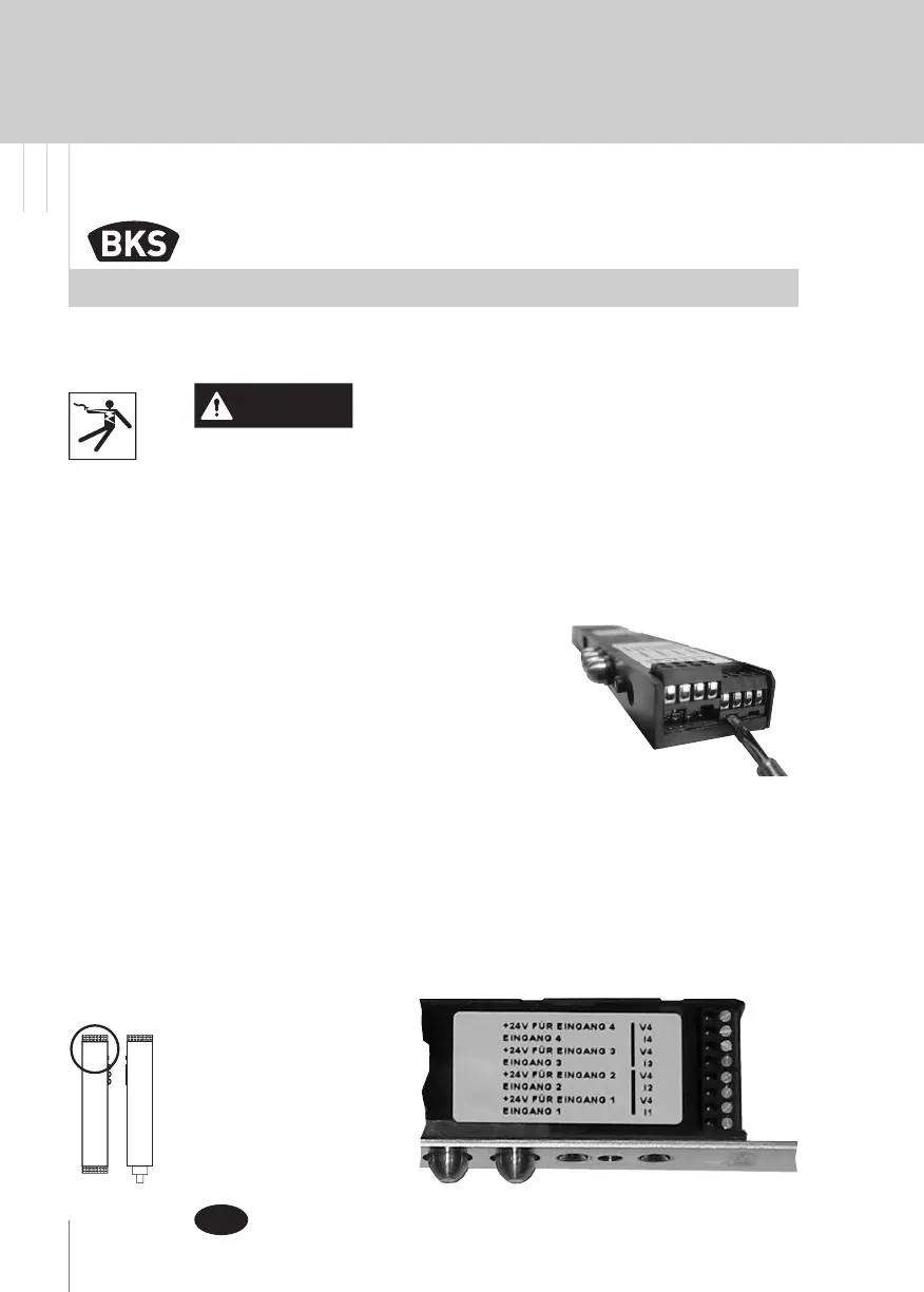
To facilitate connection, all terminals can be
disconnected from the front.
6.3 Connection terminals of SE-
CUREconnect 200F (leaf part)
6.3.1 Terminals for monitoring contacts (I1 - 14 / V4)
This is where the door monitoring contacts of the electromechanical or
motor-driven locks (if provided) are connected.
With the door closed, the feedback signals are transmitted to
SECUREconnect R (frame part) in an encrypted way and put out :
to a potential-free changeover contact via the relays of a connected I/O
module IO (optional)-
see connection diagram in
chapter .
Observe standards and regulations for extra-low
voltage (SELV) during installation and laying of
cables.
CAUTION


 To Next Page