Information in this document can be modified without notice.
Edition 07.2020 ..
03
5
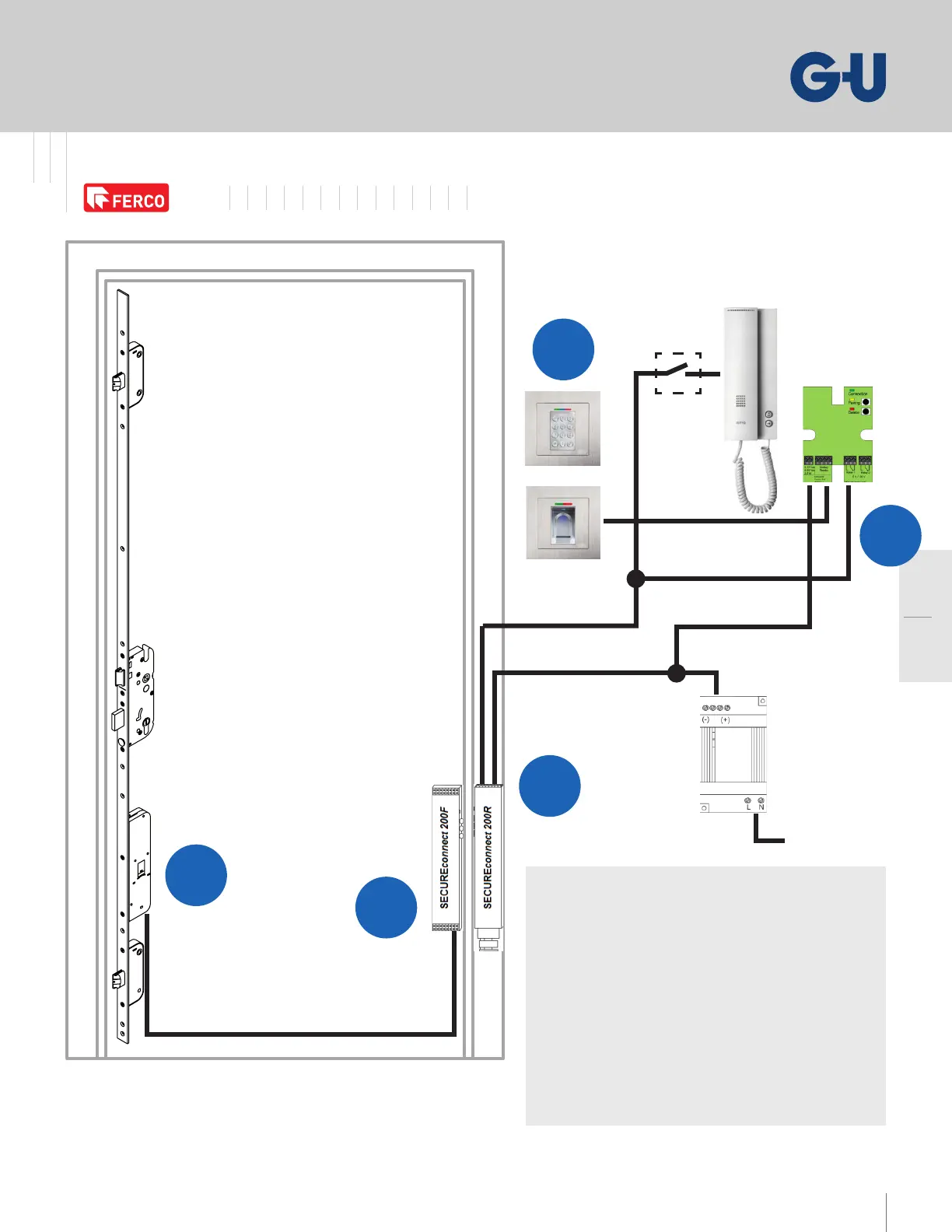
Door Multipoint Locking System
Solid brass handle & 45mm plate series
Wire Diagrams – Option 4
SECURY Automatic, A-opener, SECUREconnect ,
Code Keypad or Fingerprint Scanner, V DC
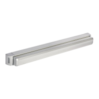
DOOR FRAME
DOOR LEAF
SECURY
Automatic
Lock
or
Term.: V /
(short term open)
Term.: V(+) / G(-)
Potential-free contact for external:
- Intercom
- Switch
Optional
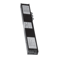
Relay-unit
(in white box)
V DC
.A
Black =
Grey = GS
Brown = VS
Door Multi-point Locking System Automatic Smart Access Controlled
I
G
C
A-opener
A
H
Code keypad kit = K-C---
Fingerprint scanner kit = K-C---
SECURY Automatic european profile cylinder lock
Faceplate for SECUREconnect = -C-XX--B
( required)
Potential-free contact = by other
Intercom = by other
Switch = by other
Power supply = -C---
V AC, Hz
WALL MOUNTED
* Do not install the SECUREconnect if conditions require a higher protection class than IP
Power Supply