7
Governors America Corp. © 2020 Copyright All Rights Reserved
ESD5500E Series Speed Control Unit 9-2020-F PIB1002
The ESD5500 series of controllers have the ability to expand the speed range by placing a jumper wire across terminals
G and J. The standard range is 7400 Hz however this is based on the operating speed and the number of ywheel teeth
(see formula). If your application is above this frequency, or near it – place the jumper and test again. This is an important step if your engine
is not able to reach rated speed but the actuator is not saturated.
NOTE
SPEED DROOP OPERATION
Droop is typically used for the paralleling of engine driven generators. When in droop operation, the engine speed will decrease as engine load
increases. The percentage of droop is based on the actuator current change from no engine load to full load.
Place the optional external selector switch in the DROOP position. DROOP is increased by clockwise rotation of the DROOP adjustment
control.
After the droop level has been adjusted, the rated engine speed setting may need to be reset. Check the engines speed and adjust that speed
setting accordingly.
Though a wide range of droop is available with the internal control, droop level requirements of 10% are unusual. If droop
levels experienced are higher or lower than those required, contact GAC for assistance.
NOTE
A single remote speed adjustment potentiometer can be used to adjust the engine speed continuously over a specic speed range.
Select the desired speed range and corresponding potentiometer value (See Variable Speed Table). If the exact range cannot be found, select
the next higher range potentiometer.
To maintain engine stability at the minimum speed setting, a small amount of droop can be added using the DROOP adjustment. At the max-
imum speed setting the governor performance will be near isochronous, regardless of the droop adjustment setting.
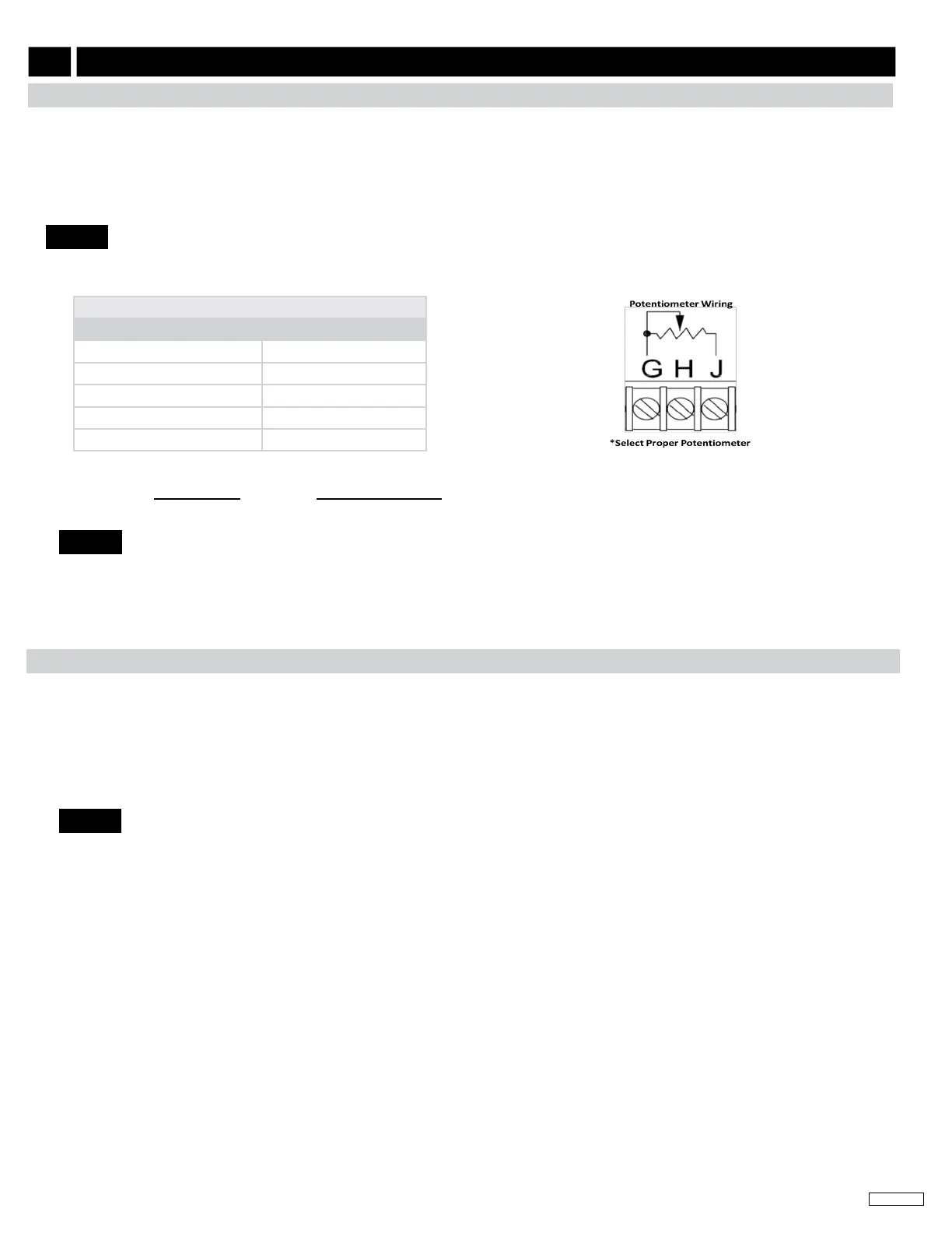
An additional xed resistor may be placed across the potentiometer to obtain the exact desired range. Connect the speed
range potentiometer as shown to the right using Terminals G and J. Contact GAC for assistance if you experience diculty
obtaining the desired variable speed governing performance.
REMOTE VARIABLE SPEED OPERATION
NOTE
VARIABLE SPEED TABLE
SPEED FREQUENCY RANGE POTENTIOMETER VALUE
900 Hz 1 kΩ
2400 Hz 5 kΩ
3000 Hz 10 kΩ
3500 Hz 25 kΩ
3700 Hz 50 kΩ
Conversion Formulas
Hertz
MAG PICKUP
=
(RPM x #Teeth)
60
RPM =
(Hertz
MAG PICKUP
x 60)
#Teeth
11
ADDITIONAL FEATURES & OPTIONAL WIRING (CONTINUED)
 Loading...