R
R
G
G
-
-
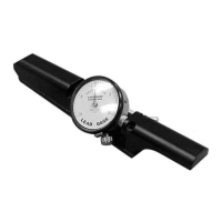
7
7
0
0
0
0
0
0
T
T
h
h
r
r
e
e
a
a
d
d
D
D
i
i
a
a
m
m
e
e
t
t
e
e
r
r
G
G
a
a
g
g
e
e
O
O
p
p
e
e
r
r
a
a
t
t
i
i
o
o
n
n
M
M
a
a
n
n
u
u
a
a
l
l
15
Zeroing the RG-7000 Gage Using the MIC TRAC
Materials Needed:
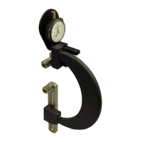
• RG-7000 gage
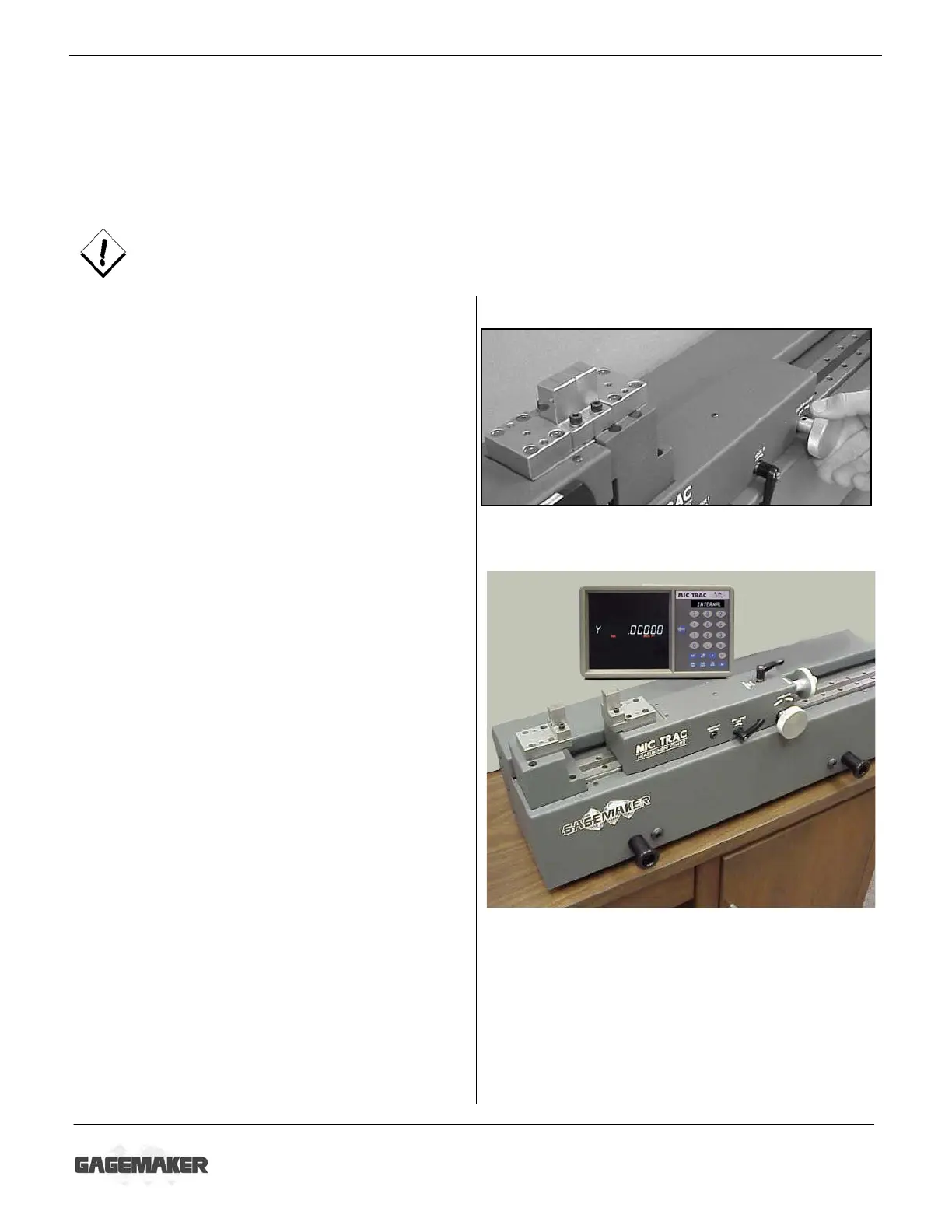
• MIC TRAC MT-3000, CPU, and flat face anvils
• 5/32” hex wrench (supplied with gage)
• Setting dimensions (Thread Disk for Windows software)
To ensure consistent and accurate readings, the RG-7000 gage should be zeroed on the MT-
3000 once during each shift, at a minimum.
1. Turn the coarse adjust knob counterclockwise
to bring the flat face anvils together.
2. If necessary for documentation purposes,
press the PRINT pad on the CPU to record
the starting location of the anvils.
3. Press the EXT pad on the CPU to change to
external measurement mode.
4. Locate the gage setting dimensions previously
printed from the Gagemaker screen in the
Thread Disk for Windows software.
5. Turn the coarse adjust knob on the MT-3000
to display a measurement that is close to the
desired setting dimension.
6. Secure the coarse adjust lock.
7. Turn the fine adjust knob until the CPU
displays the exact setting dimension.
8. Secure the fine adjust lock.
9. If necessary for documentation purposes,
press the PRINT pad on the CPU to record
the actual setting dimension.