25
CONNECTION OF POWER SUPPLY WIRES AND
SIGNAL WIRES
Outdoor unit
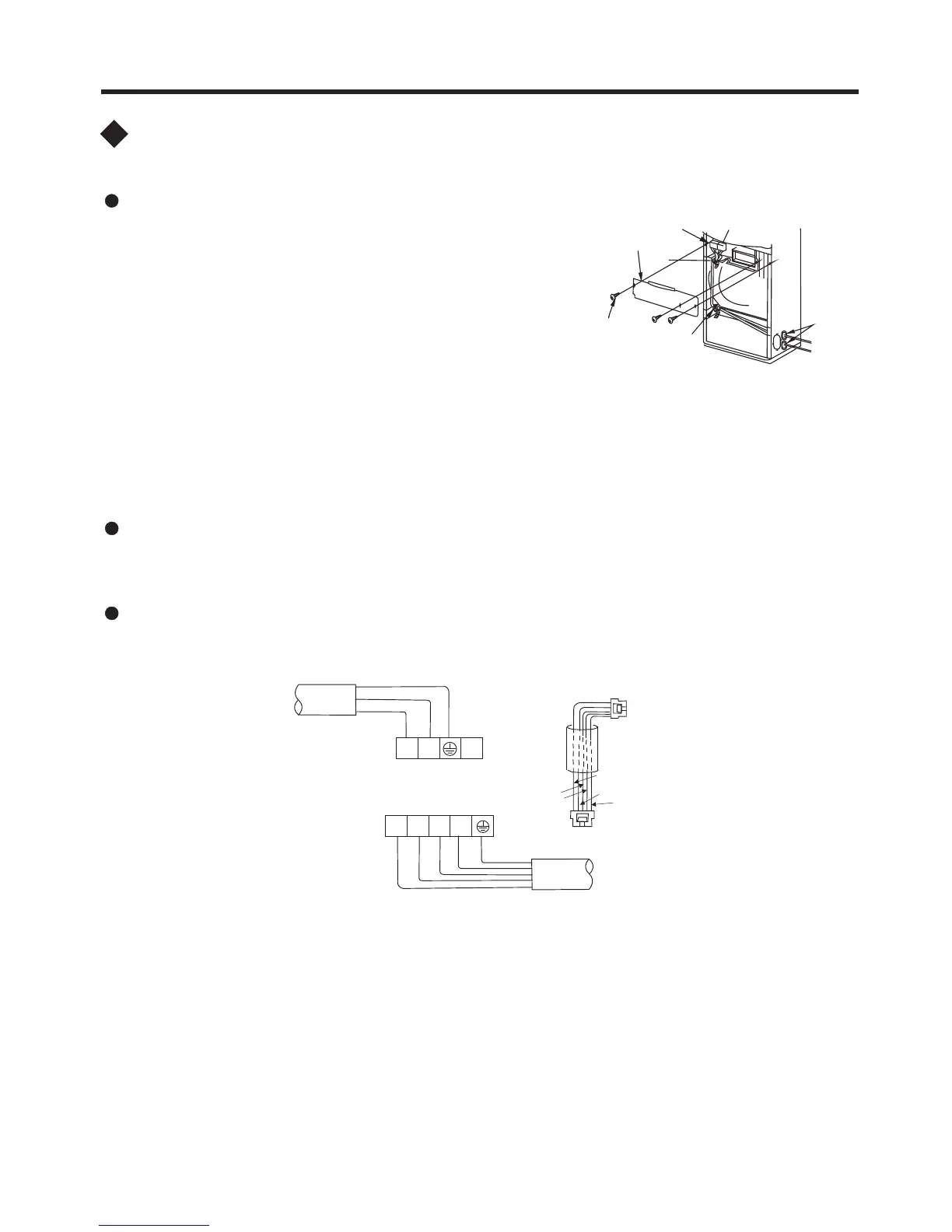
1 Remove the self-tapping screws (3 pcs) fixing the
electric box cover and take out the electric box.
2 Loosen the fixing screw of the power terminal board
and signal terminal board, then firmly fix the power
wire and signal wire on the terminal board with the
fixing screw.
3 Fix the connected wires with wire spacer and anchor
cable. The ground wire must be firmly connected.
4 Since the piping is likely to have condensate, the power wire and signal wire should
use insulation sleeve to avoid contacting the pipe. Install the electric cover.
terminal board
self-tapping
screw
electric
box cover
anchor cable
Insulation
bush for
cable
INSTALLATION INSTRUCTIONS
Wiring diagram
Indoor unit
Note:
1 If you find the color of connecting cable not comply with the top diagram, please take
real objects as major reference. But the terminal of the same sign must be joint with
the connecting cable of the same color.
2 The power wire and signal wire between the indoor/outdoor units must be connected
one by one as per corresponding number on the wiring terminal board.
3 If the signal wire has to be bought separately, choose electric wire above 0.75mm.
2
Wring route of the outdoor unit goes together with that of tubing.
Indoor unit terminal
Outdoor unit terminal
Black
Yellow/Green
Blue
Brown
Gray
Yellow/Green
Brown
power wire
2
N
L
L1
N
L3L2
Connecting
joint
Connecting
joint
Connecting cable
power wire
Blue
Brown
Blue
Black
Gray
 Loading...