IGNITION NOISE INTERFERENCE
CHAPTER 3 OPERATION
With weak signals, you may experience interference of the signal by background
noise. This radio has NB and ANL circuits which will help reduce background noise
from sources such as your ignition system. However, background electrical noise may
come from several sources and all noise may not be eliminated. With extremely weak
signals, you can operate this radio with the engine turned off, which should improve
reception. If the ignition noise level is too high to allow proper operation under most
conditions, you should have your installation of the radio checked by a qualified
technician.
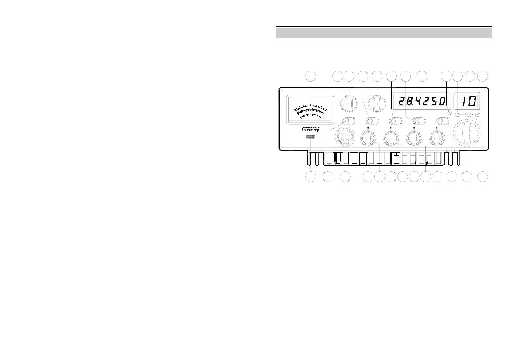
CONTROL FUNCTIONS
FRONT PANEL
ANTENNA
This radio has a jack in the rear for a standard PL-259 antenna plug. If you are
looking for the most range for your transmission, use a vertically polarized, quarter-
wave length antenna. If antenna height is a problem, you may use a shorter, loaded-type
whip antenna although you can expect some loss of transmission range.
To improve performance, your antenna should be matched to your radio. Your
antenna can be adjusted so that it matches your radio.
EXTERNAL SPEAKER
The external speaker jack (EXT SP.) on the rear panel is used for remote receiver
monitoring. The external speaker should have 8 ohms impedance and be able to handle
at least 4 watts. When the external speaker is plugged in, the internal speaker is
disconnected.
1. MOD LAMP: When switched on, this Modulation indicator will illuminate as you
speak into the microphone. When you speak louder, it appears bright because it is
on nearly 100 percent of the time and when you speak softer, it appears dimmer
because it is flickering on and off. It does not glow at all when there is no
modulation. This lamp operates in all modes.
PUBLIC ADDRESS
To use the Public Address (PA) function, first connect an external speaker to the PA.
SP. Jack on the rear of the radio. See the above specifications for a proper external
speaker. Keep the speaker away from the microphone to avoid acoustic feedback.
2. SWR/MOD/PWR SWITCH: This switch controls the function of the meter
during the transmit mode. In the “SWR” position, the meter indicates the Standing
Wave Ratio (SWR) of your antenna (accurate at maximum power output). There
are no adjustments because the SWR circuit in this radio calibrates itself
automatically. When the switch is in the “MOD” position, the green scale on the
meter indicates your percentage of modulation in the AM mode only. It is most
accurate when testing at maximum power output. When this switch is in “PWR”
position, the meter indicates your power output.
3. MICROPHONE JACK: Used to connect microphone.
4. ON/OFF VOLUME CONTROL: This knob controls the volume and power to the
radio. To turn radio on, rotate the knob clockwise. Turning the knob further will
increase the volume of the receiver.
5/6 DIGIT
NB
MOD
1
00
1
0
60
20
40
80
MOD
7
F. DISP OFF
PU SH
312
95T
DX
1
PW R
SW R
0
2
1
.5
3
MA
X
SW R
456
VO L SQ
OFF
OFF
PW R
MOD
RB
TB OFF
PU SH
MIC TB
GNF
EC H O
OFF
8 9 10 11
+10KHz
RX/TX
PU SH
NB/ANL
DIM PO W ER
LA M P
40dB
PAD
OFF
FINE COARSE
OFF
RX
1312
ANL
PAD
BIG RIG SERIES
+2
0
40
5
1
S
3
20
9
7
60
80
14
+4
0
1
00
%
+6
0
dB
A
C
B
15 18
G
H
ED
F
PA
FM
1716
LSB
AM
USB
19 2320 21 22 25
HIGH SW R ALERT
24
4
5
 Loading...