CHAPTER 1 SPECIFICATIONS
CHAPTER 2 INSTALLATION
GENERAL
Model
3
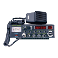
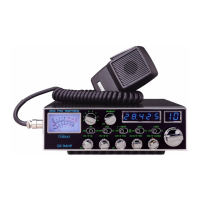
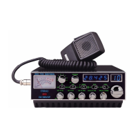
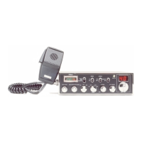
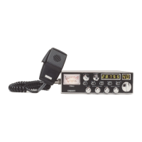
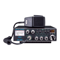
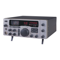
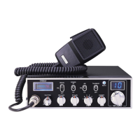
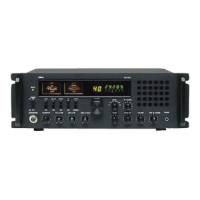
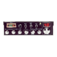
DX 95T
Frequency Range 28.315 ~ 28.755 MHz
Emission FM/AM/USB/LSB
Frequency Control Phase-Lock-Loop (PLL) Synthesizer
Frequency Stability 0.001%
Temperature Range
-30°C to +50°C
Antenna Impedance 50 Ohms
Antenna Connectors Standard SO-239 type
Input Voltage 13.8V DC
Size
7 3/4" (W) x 2 7/8" (H) x 10 1/4" (D)
Weight
6 lb.
TRANSMITTER
AM/FM: 2W~50W RF Power Output
USB/LSB: 150W PEP
Spurious Emission -50 dB
Unwanted Sideband -50 dB
Audio Distortion 10%
Frequency Response 300 to 2500Hz
Microphone Dynamic
Clarifier Range
Coarse: ± 6.0KHz, Fine: ± 1.0KHz
RECEIVER
Sensitivity for 10 dB (S+N)/N AM: < 0.5 µV; USB/LSB: < 0.25 µV
Sensitivity for 12 dB (S+N)/N FM: < 0.25 µV
Squelch Sensitivity < 0.5 uV
Selectivity -55 dB
Image Rejection -50 dB
AGC Figure of Merit 100 mV for 10dB Change in Audio Output
Audio Power Output 2.5W @ 10% Distortion
Audio Response 300 to 2500 Hz
INSTALLING THE RADIO
Choose a convenient location for operation that does not interfere with driver or
passenger. This radio is supplied with a universal mounting bracket. When mounting
the bracket and radio to your car, make sure it is mechanically strong. Also, provide a
good electrical grounding connection to the chassis of vehicle. Proceed as follows to
install the radio.
1. Locate a convenient area in your vehicle for the installation of the radio. Hold the
mounting bracket with the radio in the location where the radio is to be installed.
Make sure nothing will interfere with either the radio or the mounting bolts. Mark
and then drill holes for the mounting bracket.
2. Most radio antennas come equipped with a PL-259 plug. Connect this plug to the
ANT. Jack in the rear of the radio.
3. Extending from the rear of the radio is a fused red and black wire for the DC
connections to the vehicle’s electrical system. For best performance, it is strongly
recommended that the red lead be taken directly to the positive terminal on the
vehicle’s battery and the black lead be connected to the nearest chassis ground.
(Note: This radio is designed for vehicles with negative ground systems.)
Connections should be made using appropriate “crimp on” lugs of a size large
enough to make good contact with the bolt used to fasten to the battery and the
chassis ground. It is a good safety idea to install a second fuse that would provide
protection in case the red wire was to “fray” or get pinched and short to the body of
the vehicle, somewhere between the battery and the radio.
High power radios such as this one require large DC current flow when in the TX
mode. Poor power connections cause supply voltage drops that can substantially
decrease the performance of your radio. A good DC connection is probably one of
the most important things for getting the best transmitter performance and in some
cases, least receiver noise.
4. Mount the microphone bracket near the radio in an easily accessible spot using the
two screws provided.
(SPECIFICATIONS SUBJECT TO CHANGE WITHOUT NOTICE)
2
 Loading...