3E4465 Gallagher HBUS 8 Port Hub Installation Note | Edition 4 | January 2021
Copyright © Gallagher Group Limited Page 6
2.6 HBUS device limits
The RS485 device limits of the Controller 6000 must still be met.
2.7 HBUS LED diagnostic indications
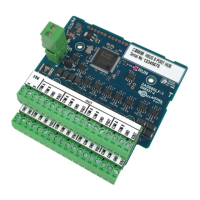
The diagnostic LED is labelled “RUN” on the HBUS 8 Port Hub.
1 Flash (Red) indicates that it is functioning normally.
3 Installation
ATTENTION: This equipment contains components that can be damaged by electrostatic
discharge. Ensure both you and the equipment are earthed before beginning any
servicing.
The Gallagher HBUS 8 Port Hub can be mounted in a Gallagher Starter Kit Cabinet (C300120), Gallagher
Cabinet (C200100) or Gallagher Dual Cabinet (C200104 or C200105).
Notes:
• The HBUS Hub should be located within an enclosure that has Tamper Detection.
• The wiring from the Controller HBUS Port to the HBUS Hub should comply with the cable
requirements of HBUS.
• The Power for the HBUS Hub should be provided from a fused source, and sufficient to supply the 8
outgoing Power Connections.
1. Refer to the appropriate Gallagher Cabinet installation note below for details regarding the
procedures involved when mounting the Gallagher Cabinet.
− Gallagher Starter Kit Cabinet Installation Note (3E3723)
− Gallagher Two Door Controller Cabinet Installation Note (3E3721)
− Gallagher Cabinet Installation Note (3C4513)
− Gallagher Dual Cabinet Installation Note (3E0694)
2. Install a Gallagher Mounting Plate (C200001, C200002 or C200003) directly into the cabinet.
3. Using the 4 pan pozi screws supplied, fit the HBUS 8 Port Hub to the installed Gallagher Mounting
Plate.
4. Connect the RS485 IN/OUT, inputs and outputs as detailed in the topic “Connections” earlier in this
note.
4 Command Centre configuration
There is no Command Centre Configuration for the HBUS 8 Port Hub, if inserted into the wiring it is
invisible to the Controller and to the HBUS devices connected to that HBUS.