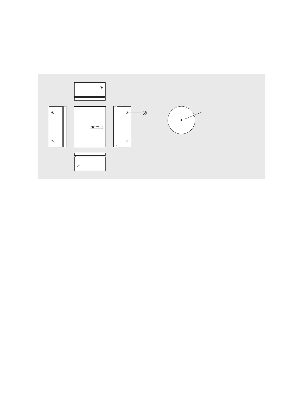
• Knockouts
The knockouts in the side panels of the cabinet can be drilled out (or 'cut out').
Each knockout has a 'dimple' in the centre to aid alignment of a drill or other cutting tool.
The knockouts are designed for use with a maximum conduit size of 25 mm (1") and for
use with PVC conduit terminators and appropriate cable glands.
Each knockout has a
centre marking hole
32
To p
Bottom
Procedure
1. Remove the gear plate from the cabinet by unscrewing the four bolts and lifting it out.
2. Identify and create the knockouts needed for the external cables. Alternatively, drill out
any additional holes needed for cable or conduit access.
3. Mark the position of the four mounting holes and rear tamper detector on the mounting
surface.
4. Fix the rear tamper sticker to the mounting surface. The sticker must align with the light
pipe located in the back of the cabinet.
5. Secure the cabinet to the wall, using a minimum of four suitable fixing anchors.
The cabinet must be tight and flush against the wall. This ensures the distance between
the rear tamper sticker and the controller's rear tamper detector is kept to a minimum.
6. Install the gear plate within the cabinet.
7. If using the Permaconn PM54, refer to the Permaconn Install Note for installation details.