3. Connect inputs and outputs
Two I/O boards are installed in the cabinet; the 8In Board, and the 8In 4Out Board.
The boards provide connection for a total of 16 inputs and 4 outputs. Two of the 16 inputs
are used for monitoring mains power failure and battery low. The remaining 14 inputs can be
used to connect sensors.
The HBUS 16In 16Out Board can be utilized with the SMB Kit to expand the solution.
Balanced inputs
Cabling should be a minimum size of 24 AWG (0.2 mm
2
) for all balanced inputs.
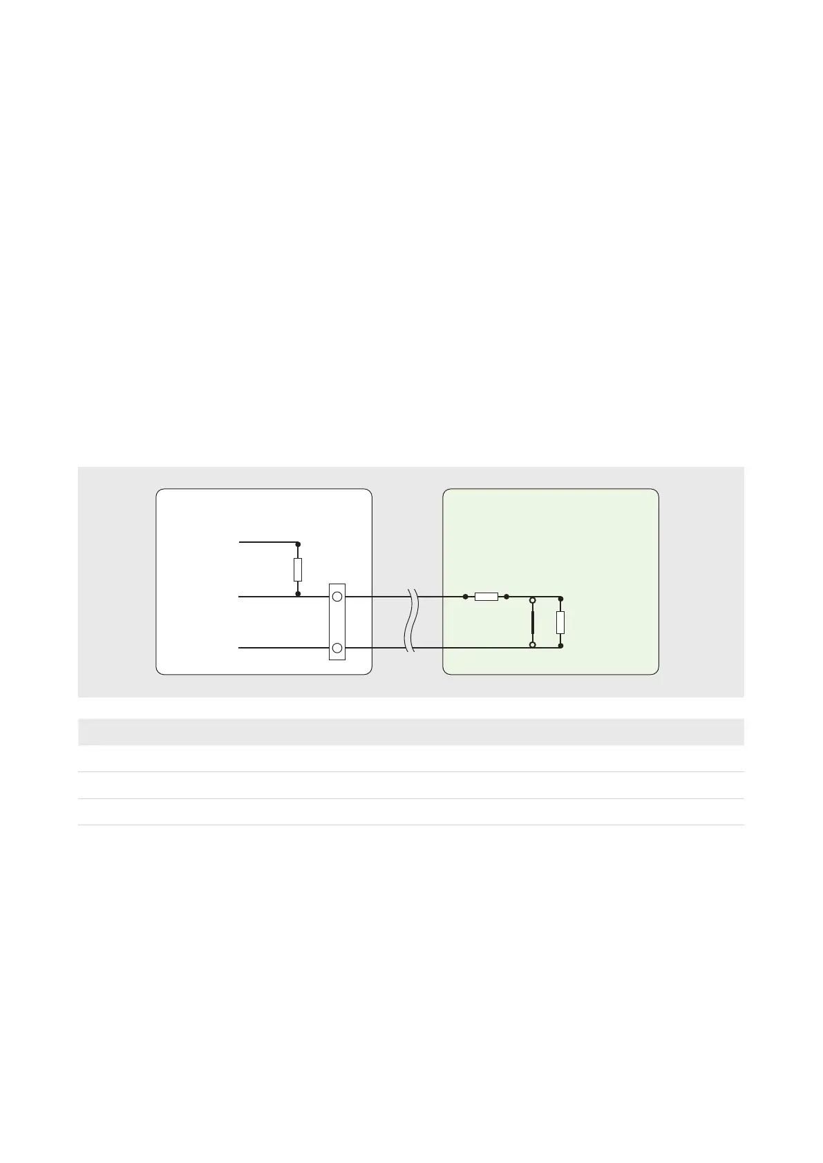
For tamper detection, the balanced inputs require resistors to be connected as close as
possible to the device being monitored. When the monitored device incorporates a normally-
closed tamper switch, it can be wired in series with resistor R1.
R1 4k7
GND
Input
Plug
5 Vdc
4k7
R2 4k7
Alarm
Sensor
Detection DeviceGallagher 8In 4Out Board
Condition Resistance Voltage at 'X'
Short circuit tamper 0
0 V
Normal 1 (4k7)
2.5 V
Alarm 2 (4k7 + 4k7 = 9k4)
3.3 V
Open circuit tamper 0 (no resistance)
5 V
All devices connected to a single I/O board must share the same physical resistor value,
(i.e. individual devices cannot have different resistors, unless assigned to different boards).
You can change the resistance value for an I/O board within the SMB Configuration App.
Additional boards can be added to the system.
Power can be drawn from the Fuse & Fire Relay Board. This board provides power distribution
and enables a fire panel to control power to a site’s doors. The board can be used to control
power to sensors and sirens, whilst maintaining circuit protection.
 Loading...