
T
Timothy GriffithAug 3, 2025
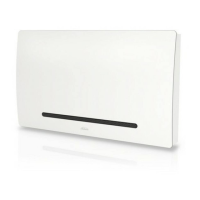
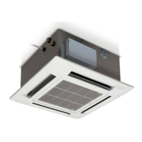
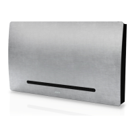
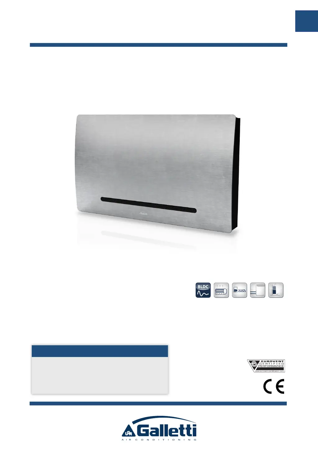
What to do if my Galletti ART-U provides insufficient cooling or heating?
- LLarry HooperAug 4, 2025
If your Galletti Heat Pump isn't providing enough cooling or heating, several factors could be the cause. Start by checking the air filter to see if it's dirty or clogged, and clean or replace it if necessary. Also, inspect the heat exchanger for dirt and clean it if needed. Ensure that there are no obstacles obstructing the air intake or outlet. Another potential issue is trapped air inside the heat exchanger, which can be resolved by bleeding it. Make sure all windows and doors are closed. Finally, check that the fan speed isn't set to the minimum; increase it if it is.