Installation
Die GT7 Terminals sind für die Montage auf einer ebenen, glatten Fläche vorgesehen.
Sie können aufputz oder halbversenkt in einem Wandausschnitt montiert werden.
Weiters können die Terminals auch halbversenkt in einer Tischplatte installiert werden.
HINWEIS!
• Empfohlene Montagehöhe gemessen bis zur Displaymitte = 1,3 m.
• Die Montage ist für das GT7.2x00 und das GT7.3x00 identisch.
• Das GT7 Terminal sollte nicht direkter Sonneneinstrahlung ausgesetzt werden.
Ansonsten kann dies zu Einschränkungen bei der Ablesbarkeit des Displays führen.
• Im Außenbereich montierten GT7 Terminals müssen die Elektroinstallation
sowie ggf. Leerrohre luftdicht abgedichtet werden (z. B. mit Silikon), damit
Kondensatbildung im Gerät vermieden werden kann.
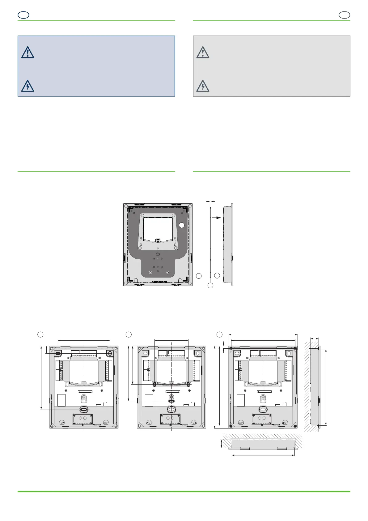
Montage des Unterteils
Wird das GT7 im Außenbereich oder an einem Ort montiert, der nicht vor
Tropfwasser geschützt ist, muss die Wanddichtung (7) verwendet werden.
1. Ziehen Sie die Schutzfolie von der
Rückseite der Dichtung ab.
2. Kleben Sie die Wanddichtung wie im
Bild gezeigt auf der Rückseite des
Untereteils auf. Achten Sie darauf,
dass die Dichtung zwischen den Kuppen
des Gehäuses flach aufliegt.
4 ...... Unterteil
7 ...... Wanddichtung
Maße in mm
3. Bohren Sie zur Befestigung des Unterteils die entsprechenden Befestigungs-
löcher in der Wand oder Tischplatte. Folgende 3 Möglichkeiten stehen zur
Auswahl:
a) Aufputzmontage ohne UP-Dose (3 Bohrungen).
b) Montage auf eine Standard 60 mm UP-Dose (3 Bohrungen).
c) Halbversenkter Einbau (Ausschnitt ca. 110 x 136 mm und 4 Bohrungen).
Maße in mm
4. Setzen Sie das Unterteil auf die Bohrungen und führen Sie dabei die
Anschlusskabel durch die mittlere Öffnung im Unterteil.
5. Schrauben Sie das Unterteil auf die Wand oder in die Tischplatte.
Installation
The GT7 terminals are designed for mounting onto a flat, smooth surface. They
can be surface mounted or semi-flush mounted in a wall cutout or, alternatively,
the terminals can be semi-flush mounted in a desk top.
NOTE!
• Recommended mounting height: 1.3 m to middle of device display.
• The mounting procedure is identical for the GT 7.2x00 and the GT7. 3x00.
• The GT7 terminal should not be exposed to direct sunlight. Otherwise,
limitations in the readability of the display can occur.
• For GT7 terminals installed outside, the electrical installation and any empty
conduits must be sealed airtight (e.g. with silicone) to prevent condensation in
the device.
Mounting the Rear Part
If the GT7 is being installed in an outdoor area or another location that is not
protected against dripping water, the wall gasket (7) must be used.
1. Remove the protective foil from the back of
the wall gasket.
2. Stick the wall gasket onto the back of the
rear part as shown in the picture to the left.
Ensure that the gasket sits flat between
the domes of the housing.
4 ......Rear part
7 ......Wall seal
Measurements in mm
3. To mount the rear part, drill the appropriate mounting holes in the wall or desk
top. The following 3 options are available:
a) Surface mounting without flush-mounted box (3 holes).
b) Mounting on a standard 60 mm flush-mounted box (3 holes).
c) Semi-flush mounting (approx. 110 x 136 mm cutout and 4 holes).
Measurements in mm
4. Align the rear part with the mounting holes while guiding the connection
cables through the central opening in the rear part.
5. Screw the rear part onto the wall or into the desk top.
Safety Instructions
- The installation and maintenance of this device must be performed
by trained, qualified personnel.
- All applicable safety and accident prevention regulations must be
observed.
- Safety devices must not be removed.
- Please observe the technical data of the device specified in this
datasheet.
- The device must be disconnected from the power supply prior to
installation, assembly, or disassemly.
Sicherheitshinweise
- Die Installation und Wartung dieses Gerätes darf nur durch
geschultes, fachkundiges Personal erfolgen.
- Die geltenden Sicherheits- und Unfallverhütungsvorschriften sind
zu beachten.
- Schutzeinrichtungen dürfen nicht entfernt werden.
- Beachten Sie die im Datenblatt angegebenen technischen Daten
des Geräts.
- Vor Arbeiten am Gerät oder Montage/Demontage muss das Gerät
spannungsfrei geschaltet werden.
DE
EN
VB_GT7-2x00-3x00--DE+EN_30 • Art.Nr.: 1100341
Gültig ab 04. Mai 2021
Technische Änderungen vorbehalten!
Seite 3
VB_GT7-2x00-3x00--DE+EN_30 • Part No.: 1100341
Valid as of 04
th
May 2021
Technical data subject to modification without notice!
Page 3
GANTNER Electronic GmbH
info@gantner.com
www.gantner.com/locations
7
4
4
7
93.1
a
b
c
14.5
113.3
13.5
122.9
114.1
110.0
14.5
146.9
142.5
4.4
135.8
60.0
68.3
98.3

 Loading...