The GAPOSA safety brake is a mechanical safety device designed for rolling shutters without springs. It serves a dual purpose: providing bearing support for the shutter shaft and acting as an anti-fall mechanism in case of sudden downward acceleration of the shutter. This acceleration typically occurs due to the breakage of a connection element between the transmission and the shutter shaft. The GAPOSA safety brake is equipped with a patented shock-absorber system to mitigate impact and includes a micro-switch that disconnects the electrical supply to the gear motor when the brake engages.
Function Description:
The primary function of the safety brake is to prevent uncontrolled descent of rolling shutters. It acts as a support for the shutter shaft during normal operation. In the event of a transmission failure or any other issue causing the shutter to accelerate downwards unexpectedly, the safety brake engages to stop the descent, thereby preventing potential damage or injury. The integrated micro-switch ensures that power to the motor is cut off immediately upon activation of the brake, adding an extra layer of safety.
Important Technical Specifications (refer to Tab. A for detailed values):
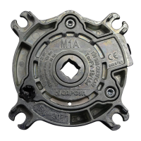
The GAPOSA safety brake range includes 9 models (M1A, P200, M3A, M4A, M7A, M10A, M15A, M20A, M30A), each with different torque capacities. The device is constructed from anti-oxidation treated materials and features a central through-hole for the shutter shaft and a metallic support base. Rubber bearings are incorporated between the central body and the base to compensate for any system eccentricity.
Key technical specifications for selecting the appropriate model include:
- Nominal Torque [Nm]: This is the reference value for selecting the most suitable safety brake based on the shutter's weight and the drive shaft's diameter. The nominal torque of the motor to be installed must fall within this value.
- Locking Torque [Nm]: This indicates the maximum stress the safety brake can withstand when it blocks the shaft's rotation.
- Working Speed [Min⁻¹]: This refers to the maximum number of revolutions at which the safety brake functions as a simple support without engaging its anti-fall mechanism. The shutter shaft's rotational speed must remain within this value.
- Screw Tightening Torque [Nm]: Specifies the required torque for tightening the fastening screws.
- Weight [Kg]: The weight of each safety brake model.
- BG-Bonn Approval: Indicates the certification status (e.g., TorFV 10/154).
- Working Temperature: The operating temperature range is -10°C to +40°C.
Usage Features:
- Installation: The safety brake must be installed with the arrow pointing in the direction of the shutter's descent. M1A and P200 models are bidirectional and can be installed on either side of the shaft. For M1A and P200, the electrical cable should face upwards (Fig. 1). The support base for M3A to M30A models should be fixed as horizontally as possible. All safety brakes must be square with respect to the vertical plane (perpendicular to the shutter's shaft), with a maximum deviation of ±3° in both directions (Fig. 1). Incorrect alignment can affect locking speed and system operation.
- Fastening: Use appropriate diameter fastening screws (4 for M1A/P200, 2 for other models) as specified in Tab. B. Shaft support pins must be welded concentrically to the shaft. The shaft support pin (with key or square for M1A and P200) should be inserted smoothly into the safety brake hole. Ensure alignment between the safety brake hole and the motor's output shaft.
- Operation: Avoid jerky shutter movements, as this may trigger the safety brake unnecessarily. A well-constructed side slide and good profiles ensure smooth operation.
- Electrical Connection: Connect the safety brake's electrical cable (which includes a micro-switch with an NC contact) to the STOP control of the gear motor's control unit (P. 28).
- Chain Transmission: If a chain transmission system is used, ensure the chain is sufficiently tight. A loose chain can cause sudden accelerations and accidental brake engagement.
- Testing: Before use, perform a thorough check of the installation, ensuring all fastening screws are properly tightened with self-locking washers and that the safety brake has not been tampered with. Verify electrical continuity at the micro-switch thread.
- Reinstatement (M1A to M10A models only): If the safety brake engages, it can be reset. Loosen the screws on the central body (Fig. 2 sequence). Push the projecting pin back to its initial position until the micro-switch reactivates (for M1A and P200, align the ring hole to the center of the slot). Lightly tighten the screws according to Fig. 2 sequence, then complete tightening with a torque wrench as per Tab. A.
- Reinstatement (M15A, M20A, M30A models): These models must be returned to GAPOSA srl for reinstatement after each activation.
Maintenance Features:
- General Maintenance: If the installation procedure is followed correctly, the safety brake does not require any specific maintenance.
- Protection: Never remove the protective bag (M3A/M4A/M7A/M10A/M15A/M20A/M30A) before installation. Do not install the safety brake outdoors without protection. Covers or boxes must shield the safety brake from external elements like rain, industrial detergents, or water jets, which could impair its functionality.
- Inspection: Do not use the device if there are signs of wear or damage, or if repair or maintenance is needed.
- During Installation: Frequently monitor the shutter/awning during installation and keep people away until the installation is complete.
- Storage: Keep these instructions for future reference.