8
2. Thesafetybrakemustbealwaysinstalledwiththearrowpointingtothedirectionin
whichtheshutterdescends;M1AandP200safetybrakeslockinbothdirectionsand
forthisreasontheycananindifferentlybeinstalledontherightorontheleftsideof
theshaft;
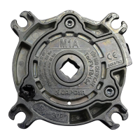
3. M1AandP200safetybrakemustbeinstalledinsquareandwiththecableonthetop
(Fig.1),thesafetybrakesbase(fromM3AtoM30A)mustbeinstalledashorizontally
aspossible;allsafetybrakesmustbeinsquareasregardstheverticallevel(perpen-
dicularlywithrespecttotheshutter’sshaft);inbothdirectionsanydeviationmust
notexceed±3°(fig.1).Awronghorizontalorverticalalignmentmayvarythelocking
speedandmaycauseabadoperationofthesystem;
4. Forthebaseusefasteningscrews(n.4forM1A/P200andn.2screwsfortheother
models)withasuitablediameter(ref.Tab.B);
5. Weldthesupportpinsoftheshaftconcentricallytoit;
6. Inserttheshaftsupportpin(withkeyorsquareincaseofM1AandP200)intothe
safetybrakeholesmoothly;eventuallycheckthealignmentbetweenthesafetybrake
hole,ononeside,andtheoutputshaftontheotherside;
7. Avoidasnappingworkingoftheshuttersinceitmightcausetheinterventionofthe
safetybrake.Awell-builtsideslideandgoodprofilesassurearegularworkingofthe
device;
8. Connectthesafetybrakeelectricalcable(completewithmicroswitchandNCcon-
tact)totheSTOPcontrolinthemotorcontrolunit(P.28);
Duringinstallation,inordertoavoidbadperformancesofthesafetybrake,donottam-
perthescrewsandtherelativenutsonthecentralbody;GAPOSAsrlisnotresponsible
fordamagescausedbyawronginstallationoranimproperuse.
TESTING INSTRUCTIONS
Thetestingprocessofthesafetybrakeconsistsof:
1. Anaccuratecheckofaperfectinstallation,bymakingsurethatallthefastening
screwsofthebaseandofthesafetybrakeareprovidedwithsuitableself-locking
washersandperfectlytightened.Makealsosurethatthesafetybrakehasnotbeen
undulyopened.
2. Acheckoftheelectricalcontinuityattheextremityofthemicro-switchthread.