Do you have a question about the GAPOSA QC400 and is the answer not in the manual?
Vertical mounting, temperature, humidity, and vibration specifications.
Covers supply voltage, transformer, motor output, and AUX output.
Details connections for safety edges, photo sensors, limits, and box dimensions.
Configures reverse time, auto close, runtimer, afterruns, and delays.
Covers service interval, reset time, and position failure monitoring.
Settings for force control parameters, including set points and frequency range.
Details the three power supply modes and required safety cut-off switch.
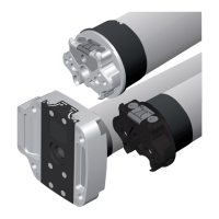
Explains how to connect the control unit to the motor using plug-in cables.
Sets Dead-man, Impulse, Auto Close, and other operational modes.
Selects limit switch type and defines safety logic for obstacle detection.
Covers service intervals, safety overrides, and special features.
Process for mechanical limits with PNE edges and deadman operation.
Programming for mechanical limits when using OSE or photocells.
Explains the meaning of Yellow, Green, and Red LEDs on the PCB for operational status.
Procedures for setting limits, encoder type, and safety equipment.
Explains the meaning of Yellow, Green, and Red LEDs on the PCB for operational status.
Details normal and special Go Function behaviors with photo safety enabled or disabled.
Procedure to disable the photo safety function before the door reaches the floor level.