4
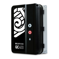
Installation
Vertical on a vibration free and flat wall
Temperature range (operating)
-10…+50°C
Humidity
Up to 93% RH non-condensing.
Vibration
Low-vibration installation, wall mounted.
Supply voltage:
(Selectable by jumper
using terminal ‘X1’)
3ph - 230/400V~ ± 10% L1,L2,L3,PE (‘N’ required ONLY for services - see par. 7/9)
1~ 230V~ ± 10% L1,N,PE
50/60Hz, Mains fuse max: 3 x 10A
Transformer
Max 10 VA , VDE 0570/EN61558
Secondary winding is overload protected by fuses.
Motor output
Max motor load by 3 x 400VAC: 2.2 kW
Max motor load by 3 x 230VAC: 1.3 kW
Max motor load by 1 x 230VAC: 0.75 kW
Emergency stop, Stop and safety jumper.
Function as normal stop command and disconnect power to contactor coil.
24VDC Output (terminals X6-8,9):
24VDC ± 20% (non-regulated), Max load: 100mA
Safety edge input:
(X5-3,4)
PNE/air switch
Electric type - 8k2 termination ± 10%
Optical type (Fraba OSE or Dalmatic TSS/RSS)
Performance level C, Category 2
Optical safety edge:
(X5-5,6,7)
Input voltage high (green): 2.5 - 5.0 Volt.
Input voltage low (green): < 0.5 Volt.
Input frequency range (green): 250 – 2000 Hz. (50% duty-cycle)
Pulse interval maximum (green): 7.0 mS (when not 50% duty-cycle)
Photo input:
(X6-9,10,11,12)
Photo, 24 VDC (e.g. self contain photo cell)
Performance level C, Category 2
Electronic limits
RS485, Data+ Data-, terminated with 120 Ohm.
Designed for Dalmatic encoder, Feig encoder and Kostal encoder (self setting)
Mechanical limits
Plug-in connector X7 for mechanical switches.
AUX solid-state relay output (X5-1,2):
NO output. Max 30V – Max 50 mA.
Box dimension
305 x 210 x 120 mm
Reversetime (Photo, Open) = 0.50 sec.
Reversetime (safety edge) = 0.25/0.1/0.05 sec.
Auto close time (Factory setup15 sec.) = 1 – 240 sec. (adaptive)
Runtimer = 120 sec.
Electronic afterrun with monitoring (DIP4 = ON) = 0.3 sec.
Min. Pullbacktime by photo, edge and force reversing
(by DIP1 and DIP2 = OFF) = 0.1 sec.
Opening counts, service interval = 1000 counts
Reset time, Service LED (active elec. Counter) = 240 sec.
Time delay before position failure (encoder is not moving) = 4.0 sec.
Dw fail afterrun = 0.5 sec.
AUX 1 setting: ON when door is stopped.
Force control (DIP5 = ON) Force control set points = 4+4
Force control delay (before measuring) = 0.8 sec.
Force control frequency range = 60 – 240 Hz
(900 – 3600 RPM with 4 pulses/rotation)
Stop by force (DIP6=OFF/ON) = -2.5/-1.0 %
Wear limit (from initial values) (DIP6=OFF/ON) = 6/5%
Automatic update of set points (force control) =
0.3%/10 Door cycles
TECHNICAL DETAILS
SOFTWARE SETTINGS
 Loading...