8 Connections
Connector
Screw
Terminal
ID
Function
LED1-
LED1+
Channel 1
output to lighting
LED2+
LED2-
Channel 2
output to lighting
PSU+
Power Supply
+ve
PSU-
Power Supply –
ve (GND)
LED3-
LED3+
Channel 3
output to lighting
LED4+
POWER/LOAD
LED4-
Channel 4
output to lighting
TRIG1-
TRIG1+
Trigger input 1
TRIG2-
TRIG A
- see
illustration
to right
TRIG2+
Trigger input 2
TRIG3-
TRIG3+
Trigger input 3
TRIG4-
TRIG B
- see
illustration to
right
TRIG4+
Trigger input 4
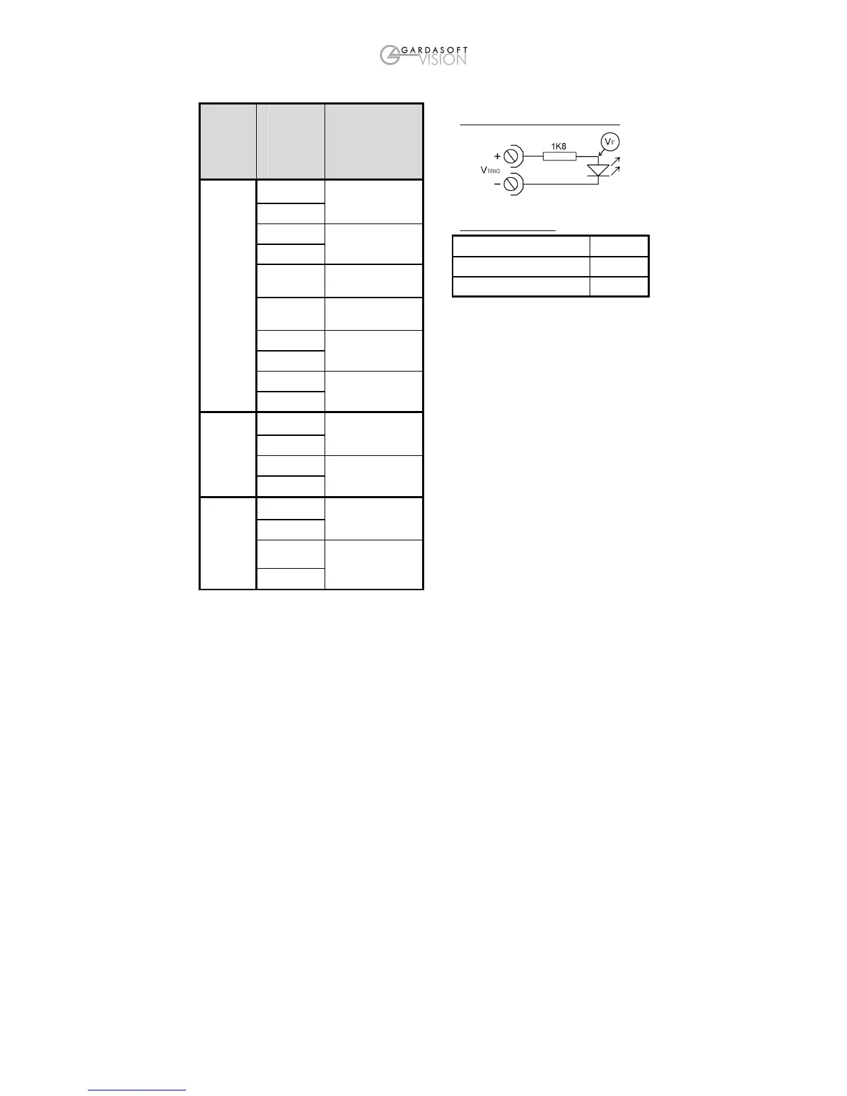
Opto-Coupled Trigger Input Details
Operating Conditions
4.5V ∗ V
TRIG
∗ 24V
Logic 1
V
TRIG
∗ 1V
Logic 0
V
F
1.5V typ
Ensure that the wire gauge used for these
connections is appropriate for the current to
be drawn. Ideally, wires should be double
crimped or independently secured to ensure
they cannot come loose. Route low voltage
and mains wiring separately. If they must be
loomed together ensure that low voltage
insulation rating is sufficient or that
supplementary insulation is used.
The PP420 has a single power input
connection (which is different from the
PP600).
Power supplies should be regulated with
SELV compliant outputs (fault tolerant).
Consideration should be given to fusing
PSU+. The fuse value can be based on the
average current output. Note that in Europe
fuses are designed to conduct at their rated
current, while in the USA fuses are designed
to blow at their rated current.
The RJ45 Ethernet connector requires a
straight through cable to connect into a
network switch, hub or router. It runs at
10Mbits per second.