15
GB
D
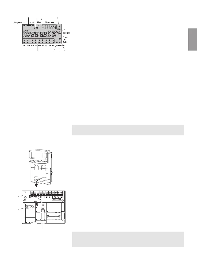
% Run-Time Function:
Duration of watering can be set between 10 - 200 % for all
channels.
E
Prog. Off
Watering programmes disabled (% Run Time function: 0%).
F
Battery Status Display:
If the Batt.-display is flashing, the battery is almost flat and
must be replaced.
If the battery display does not change, the battery is flat or none
is inserted.
The Batt.-display is reset by changing the battery.
G
Sensor Display:
If the sensor is inserted and produces the status report moist,
the sensor display appears.
H
Days of the week / Watering cycles:
To display the current day or the watering days and watering
cycles programmed (3
rd
every 3
rd
day/ 2
nd
every 2
nd
day).
I
Fault or message display:
To display a fault or message.
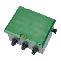
4. Putting into Operation
Before programming your Watering Controller, install a 9-V bat-
tery to prevent loss of data if a power failure occurs.
1. Raise cover
1
and pull downwards.
2. Insert the cable of the power supply unit into the 24VAC
terminals and screw tight.
The wiring diagram is located inside the cover
1
.
3. Insert cables for the valves (e. g. 7-wire GARDENA connection
cable Art. 1280 for up to 6 valves) in the clips with the numbers
and C and screw tight. (see also
“
Connect valves
”
).
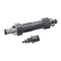
4. If necessary, insert the sensor cable (e. g. GARDENA moisture
sensor Art. 1187 ) in the sensor connection
3
.
5. If you intend to use the master channel (e. g. Art. 1273), insert
the cable for the master channel into the terminals labelled
M and C (Pump) and screw tight. (see
“Master Channel”
).
6. Insert battery into the battery compartment
2
.
Observe correct polarity.
7. Push cover on to the connection box.
8. Plug the mains plug of the 24 V (AC) power supply unit into
a 230 V mains socket.
After this it is necessary to choose between a 24 hour or
12 hour display and the time must be set (see 5. Operation
“Setting the time”
).
1
HI G F E
B C
D
9 0 A
Connecting your
Watering Controller:
0
2
3