7
6.0 MAINTENANCE
Periodic general maintenance to the bender may be required to
reduce the risk of malfunctioning rollers, sprockets, gear teeth,
and/or chains. These parts can become dirty, worn, or damaged
over time and may need to be greased or cleaned. Pressurized
air can be used to clean any dust or residue inside the bender
housing. The bender should not make any uncommon noises such
as rattling during use. If this happens, turn off the bender and
perform an inspection on the machine.
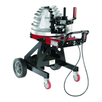
A troubleshooting aid exists on the printed circuit board mounted
to the inside of the operating handle. If all systems are functional,
a white L.E.D. (pictured in Figure 13) will flash once every two
seconds while the machine is powered up.
Error codes consist of different light patterns.
1. Blink twice = the motor is over heated.
2. Blink three times = limit switch has failed.
3. Blink 4 times = pendant control malfunction.
In addition the L.E.D. will be steady on if the bend or return button
is being pressed.
White L.E.D.
Figure 13. L.E.D. Location
7.0 TRANSPORTATION
7.1 On ground Transportation
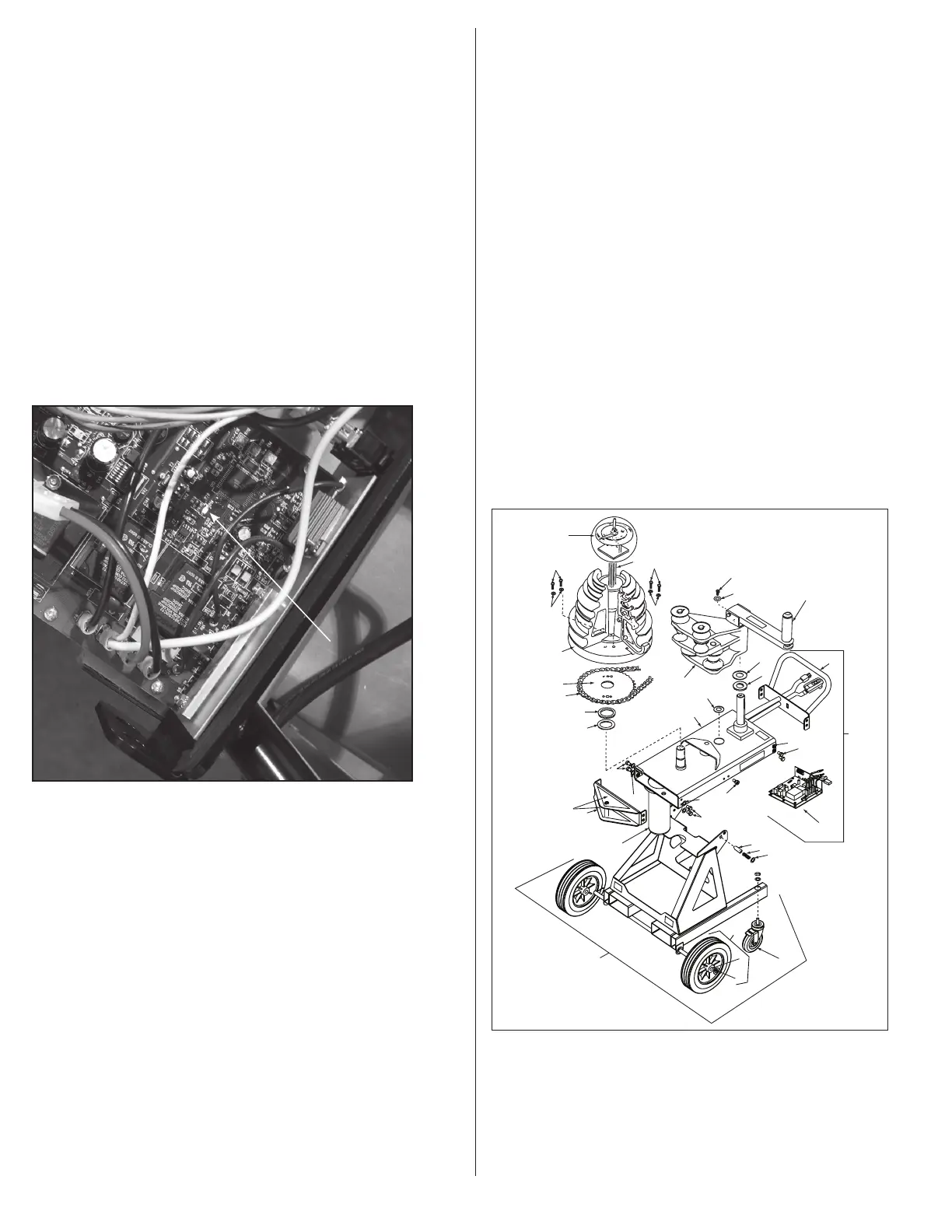
1. Rotate bender to the horizontal bending position.
a. Pull handle end of the bender to remove the preload
applied on the locking pin of the bender (Figure 14, #14),
and pull positioning pin.
b. While pulling positioning pin, carefully raise the handle end
of the bender until the sprocket housing (Figure 14, #4)
locks in the horizontal position.
2. Unlock wheels (if locked) (Figure 14, #13), and use handle
(Figure 14, #38) to push/pull bender to the desired location.
7.2 Forklift Transportation
1. Rotate bender to the horizontal bending position.
a. Pull handle end of the bender to remove the preload applied
on the positioning pin of the bender (Figure 14, #14), and
pull locking pin.
b. While pulling positioning pin, carefully raise the handle end
of the bender until the sprocket housing (Figure 14, #4)
locks in the horizontal position.
2. From the back of the bender opposite to the handle, insert forks
into fork tubes. Refer to decals located on frame for detailed
instructions.
3. Move to the desired location.
7.3 Lift/Hoist Transportation
1. If nylon sling is being used, ensure sling is long enough to
avoid contact with the bender. Bender should be hoisted in the
vertical bending position only.
2. Confirm that the Roller Housing (Figure 14, #20) and Upper
Roller (Figure 14, #12) are in place and locked.
3. Loop the nylon sling through the End Plate Lift Hook
(Figure 14, #26). DO NOT HOIST BENDER USING THE HANDLE
(Figure 14, #38).
4. NOTE: End Plate Lift Hook can also be used for job site tethering
for added security.
23
24
12
38
20
36
21
34
35
13
19
21
22
17
15
16
14
SEE INSERT A Page 3
& Fig. 6, (page 8)
4
27
34
34
37
35
35
18
(See Fig. 7)
3
Figure 1
B2000 Bender Assembly
2
9
10
9
10
1
7
8
5
6
26
11
25
Figure 14. Bender Transportation
 Loading...