4.0 OPERATION
4.1 Bending
1
⁄2",
3
⁄4" and 1" IMC, EMT and
rigid conduit:
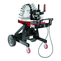
1. Position the bender in a level dry area large enough to permit
loading and unloading various lengths of conduit. Position the
frame, either horizontally or vertically, by pulling the spring
loaded pin on the side of the bender frame. See Figure 2.
Support
Arm
Positioning
Pin
Upper
Roller
Figure 2. Vertical Position
2. Identify the type (IMC, EMT or Rigid) and size conduit
to be bent.
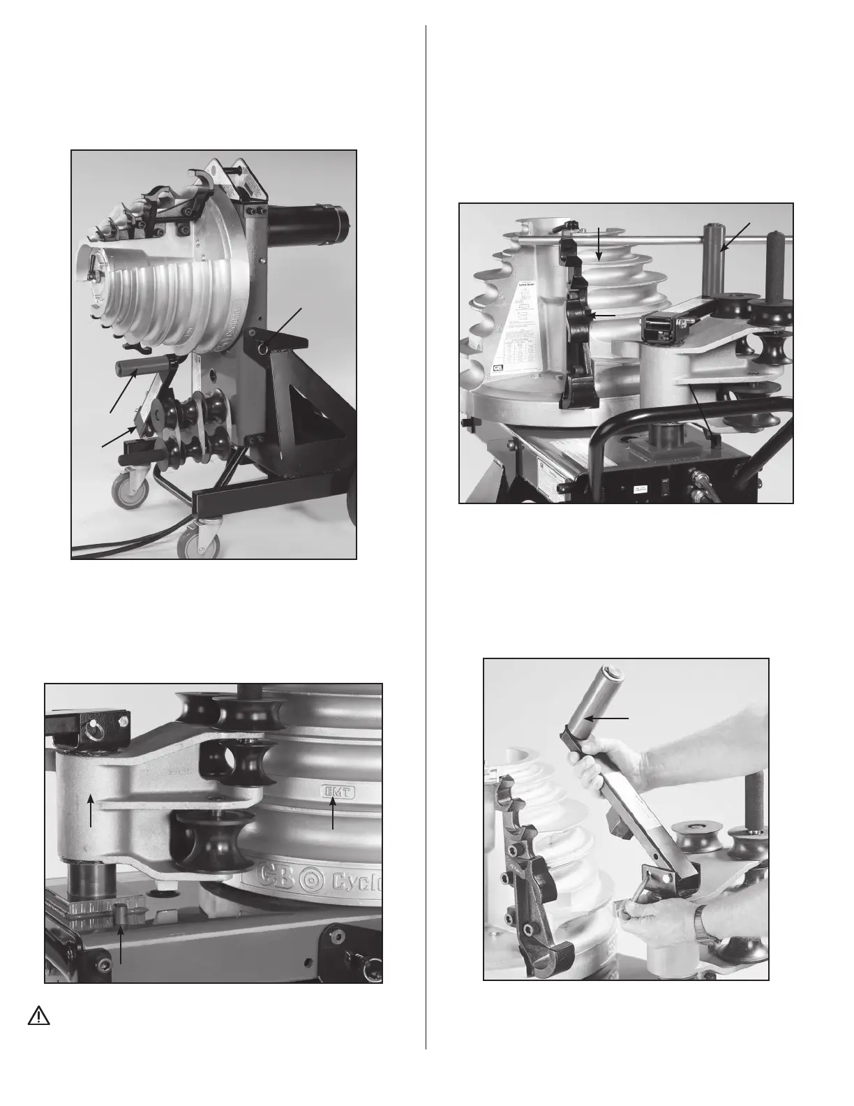
3. Locate the markings that indicate which grooves are used for
specific materials, and which grooves are used for specific
size conduit. See Figure 3.
Roller Housing
Frame Stop
Material
Identifier
Figure 3. Set Up
CAUTION: To avoid damaging the rollers and roller
housing, always place the roller housing against the frame stop
prior to rotating the shoe.
4. Push the roller housing against the frame stop.
See Figure 2. Rotate the shoe to bring the required grooves
(EMT, IMC or Rigid) facing toward the operator. To activate
the shoe, hold the pendant toggle switch in “Return” and
press the jog button until the zero light goes out. The shoe
will rotate and stop in the load position. The zero light will
come on.
5. The upper urethane roller and support arm (See Figure 4)
is used for bending
1
⁄2" through 1" conduit. One of the
top three shoe grooves will be used, depending on
conduit size.
Frame Stop
Jaw
Bend Groove
Upper Roller
Figure 4. Bending 1/2" - 1"
6. When bending
1
⁄2" - 1" conduit the upper roller and support
arm must be positioned between the shoe and the roller
housing. Position the urethane roller by moving the roller
housing against the frame stop and removing the pin.
7. Lift the roller support arm to clear the nylon rollers and swing
the arm (toward shoe) over the roller housing. Lower the arm
into the support bracket and insert the ring pin. See Figure 5.
Type Scale
Roller Support Arm
Locking Handle
Upper Urethane Roller
EMT Size Scale
Roller Support Arm
Figure 5. Position Roller Support
3
 Loading...