Offset Conduit Conduit Conduit
Required Max. Size M Max. Size M Max. Size M
2"
3
⁄4" 7
3
⁄4"
4" 1
1
⁄2" 15
7
⁄16"
3
⁄4" 8"
6" 2" 23
3
⁄16" 1" 12"
1
⁄2” 8
1
⁄2"
8" 30
5
⁄8" 1
1
⁄2" 16" 1” 11
5
⁄16"
10" 38
5
⁄8" 2" 20" 1
1
⁄4” 14
1
⁄8"
12" 46
3
⁄8" 24" 1
1
⁄2” 16
15
⁄16"
14" 54
1
⁄16" 28" 2" 19
13
⁄16"
16" 61
13
⁄16" 32" 22
5
⁄8"
18" 67
7
⁄16" 36" 25
7
⁄16"
20" 77
1
⁄4" 40" 28
1
⁄4"
22" 85" 44” 31
1
⁄8"
To locate distance between centers of offset bending marks other than
listed in table A use the following multipliers:
15° bend - 3.9
30° bend - 2.0
45° bend - 1.4
Table A
15° Bend 30° Bend 45° Bend
4.4 Stub-up Bending
1. Table C shows minimum length (inches).
2. Mark #1 is stub length, deduct from this as per table C
and obtain mark #2.
Conduit Radius Radius
Size Rigid / IMC EMT
1
⁄2" 3
31
⁄32" 3
7
⁄8"
3
⁄4" 4
25
⁄32" 4
29
⁄32"
1" 5
9
⁄16" 5
29
⁄32"
1
1
⁄4" 6
7
⁄8" 7
3
⁄32"
1
1
⁄2" 7
9
⁄16" 7
1
⁄2"
2" 8
9
⁄32" 8
9
⁄16"
Table B
BEND RADIUS
Shoe
Min. 2"
Stub Length
Set Back
Mark #2
Mark #1
Front Edge of
Clamp Mark #2
Stub to Bottom
of Pipe
1
⁄2" Rigid 7
3
⁄4" 1
1
⁄4" Rigid 12
3
⁄4"
1
⁄2" IMC 7
3
⁄4" 1
1
⁄4" IMC 12
1
⁄2"
1
⁄2" EMT 7
5
⁄8" 1
1
⁄4" EMT 13"
3
⁄4" Rigid 9" 1
1
⁄2" Rigid 13
1
⁄2"
3
⁄4" IMC 9" 1
1
⁄2" IMC 13
1
⁄2"
3
⁄4" EMT 8
1
⁄2" 1
1
⁄2" EMT 13
1
⁄2"
1" Rigid 10
1
⁄8" 2" Rigid 15
3
⁄4"
1" IMC 10
1
⁄8" 2" IMC 15
1
⁄2"
1" EMT 10
3
⁄8" 2" EMT 15
1
⁄2"
Table C
Conduit Stub-up Conduit Stub-up
Size Set-back Size Set-back
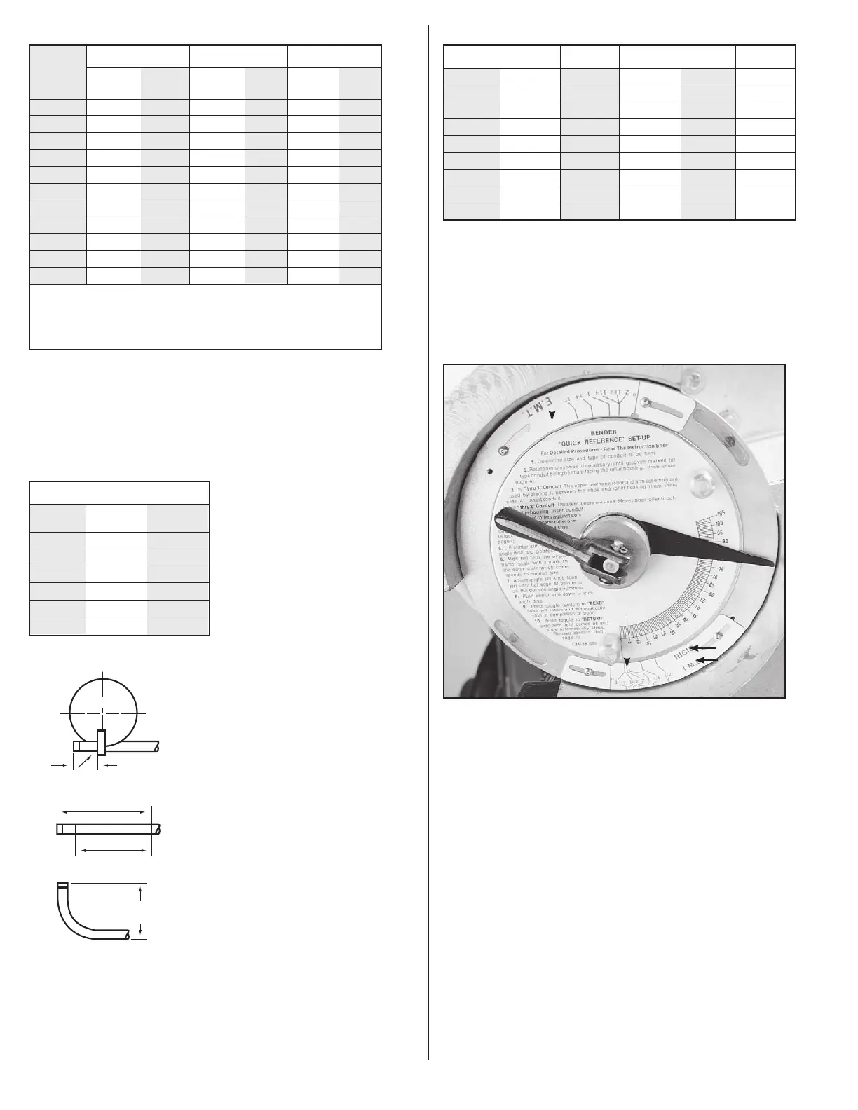
5.0 ANGLE ADJUSTMENT
Two different type scales are mounted on the shoe outer rim.
One for
1
⁄2" thru 2" IMC and Rigid, the other for EMT
1
⁄2" thru 2"
See Figure 12.
Each scale indicator is adjustable to compensate for over long
or short bends which may be due to differences in conduit
characteristics or other variations.
Type Scale
Roller Support Arm
Locking Handle
Upper Urethane Roller
EMT Size Scale
Note: Two
scales one
for rigid
and one
for IMC
Type Scale
Type Scale
Figure 12. Two Type Scales
Bends which are too long: Loosen the size scale (for type material
being bent) mounting screws. Slide the scale clockwise as many
degrees as the overbend (if bend is 5° over, move indicator 5°
clockwise). The degree of movement is observed by watching one
of the size marks as it moves past the angle disc scale. Tighten
the mounting screws.
Bends which are too short: Loosen the size scale (for type material
being bent) mounting screws. Slide the scale counterclockwise
as many degrees as the bend is short (if bend is 5° short move
counterclockwise 5°). The degree movement is observed by watching
one of the size marks as it moves past the angle disc scale. Tighten
the mounting screws.
6
 Loading...