Upper
Urethane
Roller
Nylon
Rollers
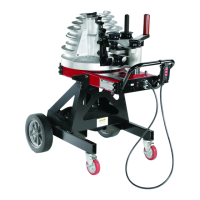
Figure 9. Locking in Roller Support
6. Each time a different size and type of conduit is being
bent, three facts must be determined and set into the
bender shoe control system. The required settings
are: conduit size, material and desired bend angle. Prior
to setting, be sure the pipe size scale is toward the
operator and the correct shoe grooves are also toward
the operator.
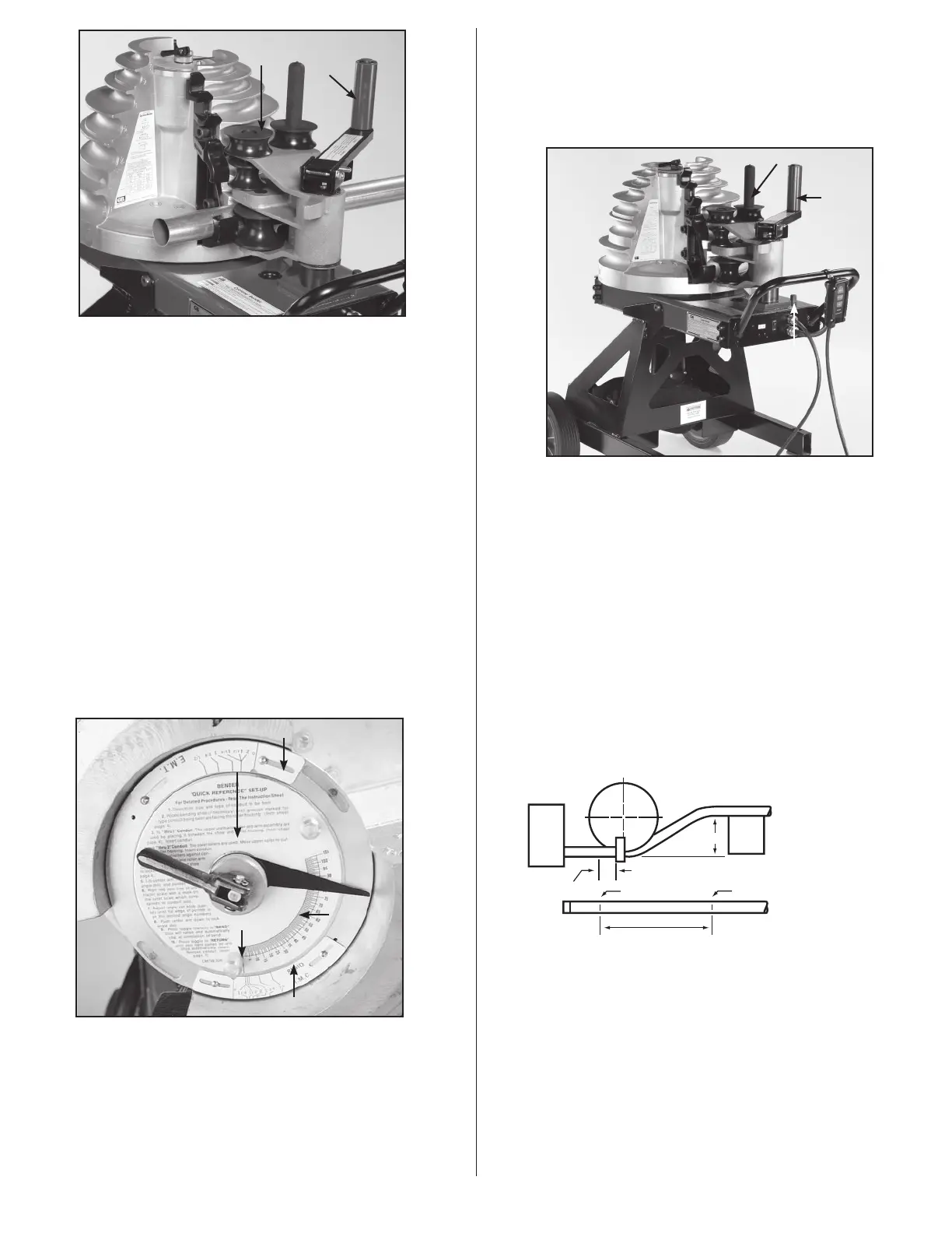
a. Lift the locking handle to release the angle set knob and
angle disc. Use the two small pins to rotate the angle disc,
clockwise. See Figure 10.
b. Set the bender for specific conduit size by turning the
angle disc until the red line is on an outer size scale mark
which matches the size conduit being bent. See Figure 10.
Be sure the correct size scale is being used (EMT, lMC, or
Rigid).
c. Move the angle set knob (See Figure 10) until the flat edge
of the pointer is on the line indicating the exact degree of
bend desired. Lower the center arm to lock the pointer,
angle disc and to prevent inadvertent movement during
bending.
Type Scale
Roller Support Arm
Locking Handle
Upper Urethane Roller
EMT Size Scale
Zero Point
Rigid/IMC Size Scale
Angle Disc
Angle Set Knob
EMT Size Scale
Figure 10. Set Angle Indicator
7. Use the control pendant. The zero light should be on. Hold
the Bend button. The shoe will rotate until the desired bend is
achieved, then stop automatically.
NOTE: If the zero light is not on, press the Return button until the
shoe stops and the zero light comes on.
8. To unload conduit, hold the Return button. The shoe will return
to the start position and stop automatically.
9. Grasp the upper urethane roller and move the support arm
clockwise until the rollers move away from the conduit. See
Figure 11. Push the roller housing against the frame stop.
Remove bent conduit.
Frame
Stop
Upper
Urethane
Roller
Roller Housing Handle
Figure 11. Unload Conduit
10. To bend more conduit of the same material and at the same
angle, load and secure as described in steps 3 through 6. To
bend the same type conduit but at a different angle, load and
secure; turn angle set knob to the desired angle, then press the
bend button.
11. Bending different type and size conduit requires repeating
steps 2 through 10.
4.3 Offset Bending
1. Obtain distance “M” from table A, and measure this distance
from mark #1 and place mark #2.
2. Now place mark #1 in line with front edge of shoe clamp and
make first bend.
3. Next rotate conduit 180° level, place mark #2 in line with front
edge of shoe clamp and make second bend.
Offset
Beam
Box
M
Front Edge of Clamp
See Ta ble A
Min. 2"
Mark #2Mark #1
NOTE: When bending rigid aluminum, set bend angle indicator
approximately 4° short of desired angle, since aluminum does not
have spring-back of steel.
5
 Loading...