This document is a Parts List, Operating, and Service Manual for Gardner Denver Sutorbilt 4500 Series Blowers.
Function Description
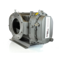
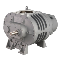
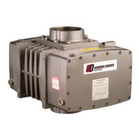
The Gardner Denver Sutorbilt 4500 Series Blowers are advanced engineering and skilled manufacturing devices designed for positive displacement. They are used in various industrial applications where reliable air or gas movement is required. The blowers feature eight-shaped impellers rotating in opposite directions inside the casing. As each lobe of an impeller passes the blower inlet, it traps a volume of air equal to exactly one-fourth the displacement of the blower. This trapped air is forced around the case to the blower outlet. Timing gears accurately position the impellers in relation to each other to maintain the minute clearances so vital to the high volumetric efficiency of the rotary positive displacement blower.
Important Technical Specifications
The manual covers "A" and "C" series blowers with 6", 7", and 8" gear diameters.
Models include:
- GDF_A_ - 6"
- GDG_A_ - 7"
- GDH_C_ - 8"
Gear Diameter and Maximum Allowable Moment:
- 6" Gear Diameter: 6.60 (A), 2.10 (B), .25 (C Max) - 4123 (LB-IN)
- 7" Gear Diameter: 7.88 (A), 3.00 (B), .25 (C Max) - 4758 (LB-IN)
- 8" Gear Diameter: 9.50 (A), 2.70 (B), .25 (C Max) - 7488 (LB-IN)
Lubrication Capacities (4500 Blower Oil Capacities):
- Vertical Configuration:
- 6" Gear Diameter: Drive End 1.5 pt., Gear End 1 qt., Total 3.5 qt.
- 7" Gear Diameter: Drive End 1.5 pt., Gear End 1 qt., Total 3.5 qt.
- 8" Gear Diameter: Drive End 3 pt., Gear End 3 qt., Total 4.5 qt.
- Horizontal Configuration:
- 6" Gear Diameter: Drive End 2.5 pt., Gear End 5 pt., Total 3.75 pt.
- 7" Gear Diameter: Drive End 5 pt., Gear End 7 pt., Total 6 qt.
- 8" Gear Diameter: Drive End 3 qt., Gear End 7 qt., Total 10 qt.
Maximum Operating Limitations:
The manual provides detailed tables for maximum RPM, Pressure PSI, and VAC in HG for various blower sizes (608, 612, 615, 618, 711, 713, 716, 721, 812, 816, 820, 824).
- Maximum Discharge Temperature for 608, 711 & 812 is 360° F (182° C).
- Maximum Discharge Temperature for 612, 615, 618, 713, 716, 721, 816, 820, 824 is 325° F (162° C).
- Blower speed, line losses, elevation, and increased inlet temperatures will affect the maximum operating limitations.
Impeller Clearances:
- 6" Blower Size:
- Min.-Max. Inches: .006-.008
- Imp. Tip Inlet/Disch Inches: .008/.006
- Discharge Open/Closed Inches: .011/.005
- 7" Blower Size:
- Min.-Max. Inches: .007-.008
- Imp. Tip Inlet/Disch Inches: .010/.006
- Discharge Open/Closed Inches: .013/.006
- 8" Blower Size:
- Min.-Max. Inches: .007-.008
- Imp. Tip Inlet/Disch Inches: .011/.006
- Discharge Open/Closed Inches: .014/.006
Usage Features
Installation:
- Foundations: Permanent installations require concrete foundations. The equipment should be grouted to the concrete. A suitable base, such as a steel combination base under the blower and motor, or a separate base plate under each, is recommended.
- Vertical and Horizontal Configurations: The manual provides detailed diagrams for various drive and hand configurations (Bottom Hand Drive, Top Hand Drive, Right Hand Drive, Left Hand Drive) for both vertical and horizontal installations.
- Drive Installation: Large blowers are generally driven by a coupling. The direct connected units, adjustments and lubrication of couplings to the specifications of the coupling manufacturer are very important. When mounted drivers are supplied from the factory, proper alignment has been established before shipment.
- Piping: Inlet and discharge connections on all blowers are large enough to handle maximum volume with minimum friction loss. Reducing the pipe diameter can either increase the overall pressure differential, causing increased power and temperature rise, or create additional line loss.
- Drive Design: When selecting a V-belt drive, check to be sure the shaft overhung load limitation is not exceeded. Belt drives must be carefully aligned.
Operation:
- Startup Procedure: A detailed blower startup checklist is provided, including checks for piping, alignment, V-belt drive, adequate drive guards, oil level, electrical power, motor rotation, internal surfaces, unit operation at no load, and proper lubrication.
- Shut Down: The blower should be unloaded before shut down. Consideration should be given to possible backflow and reverse rotation of the discharge side of the unit. A check valve is recommended.
- Operating Limitations: Do not operate equipment without adequate silencing devices installed since high noise level may cause hearing damage. Operating beyond the specified operating limitations will result in damage to the unit.
Maintenance Features
Lubrication:
- Recommended Lubricants: AEON PD Synthetic Lubricant or AEON PD-Food Grade Synthetic Lubricant.
- Lubrication Instructions: Remove vented breathers. Do not remove any other plugs from the headplates. Fill drive end until oil reaches the centerline of the sight glasses. Fill gear end until oil reaches the centerline of the sight glasses.
- Oil Change Intervals:
- Initial change: 100 hours.
- Subsequent changes: 6000 hours or annually, whichever comes first.
- For continuous operation where the lubricant temperature exceeds 200° F, the lubricant interval is recommended to be 200 hours.
- Ambient Temperature Guidelines: Detailed tables for lubricant selection based on ambient temperature (less than 10° F, 10° F to 32° F, 32° F to 90° F, greater than 90° F) are provided.
Air Filters and Filter Silencers:
- Servicing the air filters is one of the most important maintenance operations to be performed to insure long blower life.
- No matter what type of filter is used, always make sure all seats, gaskets, clamps and hose connections on the filter and inlet line are absolutely air tight. Each time the filter is serviced, inspect the interior of the blower for dirt.
Gear Inspection:
- Inspection of the timing gears may be accomplished simply by removing the gear case. Remove the bolts from the gear case and detach it from the head plate. Timing gears and gear end bearings are now exposed. On completion of maintenance work, be certain that the gear case is sealed by using a paste-type gasket compound on the mating surfaces. Always relubricate before starting.
Impeller Inspection:
- Series 4500 impellers can be inspected through the inlet or outlet ports. This will reveal such conditions as out of time, excessive or insufficient clearances, abrasion of parts from passing foreign material, etc.
- When rotation of the impellers is required in the assembly process, insure that all personnel are clear of lobes and gears to guard against serious injury.
Timing:
- The impellers of the unit are separated by pre-determined exact clearances built into the machine. The timing is built in at the setting of one impeller with respect to the other so they do not touch or knock during normal operation. The impellers are held "in time" by timing gears which are secured to the shaft by grip rings inside the gear hubs.
Resetting Impeller Clearance:
- Impellers are held in time by timing gears, which are secured in position on the impeller shafts by grip rings inside the gear hubs. To reset impeller clearances (timing) it is necessary to release the grip rings in one of the gears.
- Use a gear puller to withdraw the gear about 1/8 inch, then lightly tap the side of the gear with a mallet. This will release the grip rings inside the gear hub so that the impeller will be free to adjust. Do not remove the gear.
Bearing and Seal Replacement:
- Remove the gear case (see "Gear Inspection," page 14). Note the end clearance between the impeller and gear headplate. Remove the timing gears as instructed previously.
- Shims are installed during manufacture to set the end clearance between the impeller and headplate.
- The mechanical seal should be assembled into the bearing cartridge. Lubricate the recess and press in assembly.
- Replace the bearings and slinger. Rotate shafts a couple of turns to be sure there will be no interference of the oil slinger. Remove the end drive seal and install the gasket and drive cover. Use a paste-type gasket compound between cleaned mating surfaces. Replace the drive seal.
Troubleshooting:
The manual includes a comprehensive troubleshooting guide with common problems, possible causes, and solutions, such as:
- Knocking: Distortion due to improper mounting or pipe strains, excessive pressure differential, worn gears, worn bearings, worn bearing cartridges. Solutions include re-time impellers, check mounting alignment, reduce pressure differential, replace timing gears, bearings, and cartridges.
- Excessive blower temperature: Too much oil in gear case, too low operating speed, clogged filter or muffler, excessive pressure differential, worn impeller clearances, internal contact. Solutions include reduce oil level, increase blower speed, remove cause of obstruction, reduce pressure differential, replace impeller, correct clearances.
- Impeller end or tip drag: Insufficient assembled clearances, case or frame distortion, excessive operating pressure, excessive operating temperature. Solutions include correct clearances, check mounting and pipe strain, remove cause.
- Lack of volume: Slipping belts, worn clearances. Solutions include tighten belts, re-establish proper clearances.
- Excessive bearing or gear wear: Improper lubrication. Solution is to correct lubrication level and replace dirty and/or improper oil.
- Loss of oil: Headplate, gear case or drive cover vents plugged, worn seal. Solutions include clean vents, replace seals.
- Lack of oil pressure: Dirty suction screen, leak in suction line, lubrication pump losing its prime. Solutions include clean suction screen, repair leak, re-prime by removing pipe plug and priming.
Warranty:
Gardner Denver warrants its products to be free from defects in material and workmanship for 12 months from date of initial use or 18 months from date of shipment, whichever occurs first. The warranty is expressly exclusive and is expressly agreed that, except as to title, the company makes no other warranties, expressed, implied or statutory, including any implied warranty of merchantability.