Do you have a question about the Gardner Denver ELECTRA-SAVER and is the answer not in the manual?
Guidance on how to order replacement parts and remanufactured airends for compressors.
Details prohibitions, mandatory actions, and safety label meanings for operational awareness.
Essential safety guidelines and precautions for operating and maintaining the compressor unit.
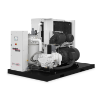
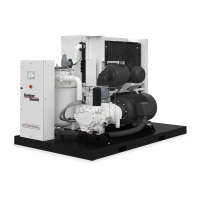
Description of the compressor, its working principle, and system airflow.
Details on the oil system for lubrication, cooling, and sealing the compressor.
Covers lifting, location, foundation, enclosure, and general setup for installation.
Guidelines for installation in cold weather and extreme cold weather conditions.
Details on service lines, heat exchangers, aftercoolers, and piping configurations.
Essential steps before operating the unit, including oil checks and filter replacement.
Procedures for safely starting and stopping the compressor unit.
Instructions for adjusting target pressure, unload, and load pressures on the controller.
How to operate the compressor using the AirSmart controller and its features.
Details on essential control devices like relief valves, blowdown valves, and starters.
Electrical wiring diagram for Wye Delta configurations at 200, 230, 460V.
Electrical wiring diagram for Wye Delta configurations at 575V.
Electrical wiring diagram for Full Volt configurations at 200 & 230V.
Electrical wiring diagram for Full Volt configurations at 460V.
Electrical wiring diagram for Full Volt configurations at 575V.
Electrical wiring diagram for Less Starter configurations at 200, 230, 460V.
Electrical wiring diagram for Less Starter configurations at 575V.
Electrical wiring diagram for Wye Delta configurations at 200/230V.
Electrical wiring diagram for Wye Delta configurations at 380/460V.
Electrical wiring diagram for Wye Delta configurations at 575V.
Electrical wiring diagram for Full Volt configurations at 200 & 230V.
Electrical wiring diagram for Full Volt configurations at 380/460V.
Electrical wiring diagram for Full Volt configurations at 575V.
Electrical wiring diagram for Less Starter configurations at 200, 230, 380, 460V.
Electrical wiring diagram for Less Starter configurations at 575V.
Explanation of the compressor's oil system, lubricants, and specifications.
Steps for lubricant change, oil level checks, and system draining and cleaning.
Details on the oil filter, oil cooler, and oil separator components.
Guidelines for servicing the heavy-duty air filter and its element life.
Procedures for assembling and replacing the flexible coupling between the motor and airend.
Scheduled maintenance tasks categorized by operating hours and time intervals.
Troubleshooting guide for common problems like starting, stopping, pressure, and temperature issues.
Addressing issues related to oil consumption, delivery, pressure, and discharge temperature.
Diagnosing and resolving problems associated with oil carryover in the system.
Outlines the warranty terms, limitations, and disclaimers for the compressor unit.
| Brand | Gardner Denver |
|---|---|
| Model | ELECTRA-SAVER |
| Category | Air Compressor |
| Language | English |