EasyManua.ls Logo

Gardner Denver RSD Series User Manual

Gardner Denver RSD Series
48 pages
To Next Page IconTo Next Page
Page #1 background imageLoading...
Page #1 background image
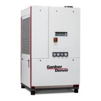
REFRIGERATED
TYPE
COMPRESSED
AIR DRYERS
5001368 Rev. M 12/17
18-2-645 3rd Edition
INSTRUCTION MANUAL
RSD SERIES
Models: RSD800, RSD1000, RSD1250,
RSD1500, RSD1750, RSD2000,
RSD2500, RSD3000
For Sales and Service: (800) 883-2477
Or visit Sales and Service at www.gardnerdenverproducts.com

Questions and Answers:

Gardner Denver RSD Series Specifications

General IconGeneral
ModelRSD Series
CategoryDehumidifier
Power Supply115V or 230V, 50/60 Hz (Varies by model)
Operating TemperatureVaries by model, typically 33°F to 100°F (1°C to 38°C)
DimensionsVaries by model
WeightVaries by model

Summary

1.0 Installation

1.1 Location

Guidance on selecting a suitable installation site for the dryer.

1.2 Mounting

Instructions for securely mounting the dryer unit.

1.3 Piping Connections

Details on connecting air and water lines to the dryer.

1.4 Electrical Connections

Guidelines for making proper electrical connections to the dryer.

1.5 Electronic Demand Drain

Explanation of the automatic drain system for condensate removal.

2.0 Operation

2.1 Minimum/Maximum Operating Conditions

Specifies the operational limits for pressure and temperature.

2.2 Start-Up

Step-by-step instructions for starting the dryer.

Control Panel Overview

Description of the dryer's control panel buttons and functions.

Starting Dryer Procedure

Detailed procedure for starting the dryer and compressor.

Operating Check Points

Essential checks to perform after starting the dryer for proper operation.

2.3 RS-485 Port Communication

Instructions for connecting and using the RS-485 communication port.

2.4 USB Host Feature

Guide on utilizing the USB port for data logging and software updates.

USB Data Logging

How to log dryer operating data using a USB flash drive.

USB Event History

Accessing and interpreting event logs stored on a USB drive.

USB Bootloader

Procedure for updating dryer firmware using a USB drive.

2.5 Ethernet Feature

Connecting and monitoring the dryer via Ethernet and web interface.

Web Interface Navigation

Navigating the dryer's web interface for monitoring and control.

Modbus TCP Connection

Using Modbus TCP for continuous monitoring via a DCS system.

3.0 Maintenance

3.1 Monthly Maintenance

Routine tasks for monthly upkeep of the dryer.

3.2 Annual Maintenance

Periodic tasks for annual maintenance and servicing.

C. Replace the filter cartridges

Steps for replacing filter elements in the separator/filters.

4.0 Troubleshooting Guide

Troubleshooting Symptoms

Identifies common symptoms and their potential causes and solutions.

5.0 Reference

Sizing

How to determine dryer capacity based on operating conditions.

Engineering Data Tables

Technical specifications and data for various dryer models.

Dryer Set Point Table

Configuration settings and default values for dryer operation.

Dryer Alarm Table

Lists all alarms, triggers, and corresponding actions.

6.0 Dimensions / Weights

Dimensions and Weights

Physical dimensions and weight specifications for each model.

7.0 Electrical Schematic

Model 800 - Sheet 1 of 2

Electrical wiring diagram for the Model 800 dryer, part 1.

Model 800 - Sheet 2 of 2

Electrical wiring diagram for the Model 800 dryer, part 2.

Models 1000 and 1250 - Sheet 1 of 2

Electrical wiring diagram for Models 1000 and 1250, part 1.

Models 1000 and 1250 - Sheet 2 of 2

Electrical wiring diagram for Models 1000 and 1250, part 2.

Models 1500 and 1750 - Sheet 1 of 2

Electrical wiring diagram for Models 1500 and 1750, part 1.

Models 1500 and 1750 - Sheet 2 of 2

Electrical wiring diagram for Models 1500 and 1750, part 2.

Models 2000 and 2500 - Sheet 1 of 2

Electrical wiring diagram for Models 2000 and 2500, part 1.

Models 2000 and 2500 - Sheet 2 of 2

Electrical wiring diagram for Models 2000 and 2500, part 2.

Model 3000 - Sheet 1 of 2

Electrical wiring diagram for the Model 3000 dryer, part 1.

Model 3000 - Sheet 2 of 2

Electrical wiring diagram for the Model 3000 dryer, part 2.

Transformer Pack Schematics

Wiring diagrams for 575-460V and 230-460V transformer packs.

8.0 Replacement Parts: Air-Cooled Units

Replacement Parts: Air-Cooled Units

Illustrated list of replaceable parts for air-cooled models.

Maintenance Kits and Parts List

Specific maintenance kits and part numbers for air-cooled units.

Replacement Parts: Water-Cooled Units

Replacement Parts: Water-Cooled Units

Illustrated list of replaceable parts for water-cooled models.

Maintenance Kits and Parts List (Water-Cooled)

Specific maintenance kits and part numbers for water-cooled units.

Replacement Parts: Cabinet Panels

Cabinet Panels

Part numbers for various cabinet panel components.

Warranty

Warranty Terms and Conditions

Details on product warranty coverage, limitations, and duration.

Related product manuals