EasyManua.ls Logo

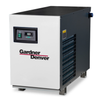
Gardner Denver RNC400 User Manual

Gardner Denver RNC400
52 pages
To Next Page IconTo Next Page
Page #1 background imageLoading...
Page #1 background image
REFRIGERATED
TYPE
COMPRESSED
AIR DRYERS
INSTRUCTION MANUAL
RNC Series
Models: RNC100, RNC125, RNC150, RNC200,
RNC250, RNC300, RNC400, RNC500,
RNC600, RNC750
5002737 Rev. J 02/17
18-2-670 RNC100-750 New Platform 1st Edition
For Sales and Service: (800) 883-2477
Or visit Sales and Service at www.gardnerdenverproducts.com

Table of Contents

Questions and Answers:

Gardner Denver RNC400 Specifications

General IconGeneral
BrandGardner Denver
ModelRNC400
CategoryDehumidifier
LanguageEnglish

Summary

General Safety Information

Pressurized Devices Safety

Safety precautions for pressure-containing equipment.

Electrical Safety Precautions

Safety guidelines for electrical operation and service.

Installation Guide

Piping Connections

Details on connecting air inlet, air outlet, and water lines.

Electrical Connections

Guidance for making proper electrical connections to the dryer.

Operation Procedures

Start-up Sequence

Step-by-step instructions for safely starting the dryer.

I-Controller Level 4 Operation

Detailed instructions for operating the I-Controller Level 4.

Manual and Schedule Mode Operation

Operating the dryer in manual or scheduled modes.

Starting and Operating Checkpoints

Procedures for starting the dryer and performing operational checks.

Modbus Register Reference

Table of Modbus registers for dryer data and control.

Maintenance Procedures

Troubleshooting Guide (I-Controller Level 1 & 2)

Refrigeration System Malfunctions

Diagnosing issues with the refrigeration system not functioning.

Troubleshooting Guide (I-Controller Level 4)

Level 4: Checkpoint Faults

Diagnosing faults and alarm conditions for Level 4 controller.

Reference Information

Dryer Alarm Conditions and Actions

List of alarm conditions, triggers, and corresponding actions.

Wiring Diagrams

I-Controller Level 1

Electrical wiring diagram for I-Controller Level 1, Model 100.

I-Controller Level 2 (Model 100-150)

Electrical wiring diagram for I-Controller Level 2, Models 100-150.

I-Controller Level 2 (Models 200-600, Sheet 1)

Electrical wiring diagram for I-Controller Level 2, Models 200-600 (Sheet 1).

I-Controller Level 2 (Models 200-600, Sheet 2)

Electrical wiring diagram for I-Controller Level 2, Models 200-600 (Sheet 2).

I-Controller Level 4 (Model 750, Sheet 1)

Electrical wiring diagram for I-Controller Level 4, Model 750 (Sheet 1).

I-Controller Level 4 (Model 750, Sheet 2)

Electrical wiring diagram for I-Controller Level 4, Model 750 (Sheet 2).

I-Controller Level 4 (Models 200-600, Sheet 1)

Electrical wiring diagram for I-Controller Level 4, Models 200-600 (Sheet 1).

I-Controller Level 4 (Models 200-600, Sheet 2)

Electrical wiring diagram for I-Controller Level 4, Models 200-600 (Sheet 2).

Product Warranty Information

Related product manuals