Do you have a question about the GARDTEC 800 Series and is the answer not in the manual?
Details on user code types for Gardtec 872 and 800/816 models, including Master, Main, and Cleaner roles.
Distinction between global codes controlling all areas and area codes for specific zone control.
Explanation of 16(2 Wire), 8(4 Wire), and 16(EOL) zone wiring modes for system setup.
Information on adding zones via expander cards, including ID and Radio expansion capabilities.
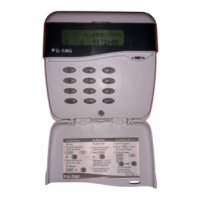
Overview of available keypad types (LCD, LED, ACE) and their operational functions like log viewing.
Guidance on remote system management capabilities for uploading and downloading panel configurations.
Considerations for choosing master control panel and remote keypad locations for optimal system design.
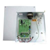
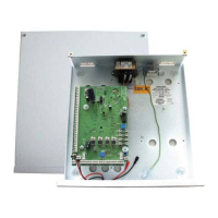
Step-by-step instructions for securely mounting the control panel base and lid.
Details on mounting standard and contour keypads, including housing positions and tamper switch setup.
Guidelines for safely connecting the mains power supply, including earthing requirements.
Explanation of 'Star' and 'Daisy Chain' wiring formats for connecting multiple keypads to the system.
Instructions for configuring keypad numbering (ident) and jumper settings for LCD/LED versions.
Details on connecting ACE receivers and configuring their jumper settings for system integration.
Comprehensive guide to 8(4 Wire), 16(2 Wire), and 16(EOL) zone connection methods.
Procedure for installing and identifying zone expander cards, including wiring configurations.
Guide to configuring Output Expander Modules (OPX) for custom output assignments.
Instructions for wiring and programming ID expander cards and biscuits for enhanced zone capacity.
Details on connecting and configuring Radio Expanders (ZEX) for wireless detector integration.
Explanation of how zones can be allocated to multiple areas, forming common areas.
Definitions of various zone types including Access, Entry/Exit, Panic, Fire, and Line Fault.
Description of general and communication output types, such as Pulse, Alarm, and Digicom channels.
Introduction to programming the system using LCD keypads and engineer codes.
Procedures for resetting system settings to factory defaults, including essential reset steps.
Guidance on moving through programming headers and options using keypad navigation.
List of shortcut menu numbers for quick access to common programming options.
Explanation of Part Set modes, Test zones, and Chime functionality for system setup.
Step-by-step guide for programming individual zones, including types, areas, and descriptors.
Configuration of system setting modes like Set By Time, Set By ET, and Set By E/E.
Setting up Entry Time 1 and Entry Time 2 parameters for system access and alarms.
Configuration of bell types (SAB/SCB), delay, ring time, and sounder levels.
Setting up keypad alert keys, number of keypads, and ACE/Prox integration.
Configuration of Digicom types, Modem modes, and STU adaptor settings for communication.
Setting up linefault sounders, detection modes, and log settings for fault reporting.
Configuration of Panic (PA) and Duress signal behavior, including bell and central station transmission.
Setting up relay and PGM3 outputs, and configuring programmable timers for system functions.
Configuration of system reset modes, including mains fail delay and tamper reset settings.
Adjusting sounder levels for chime, entry/exit, and key beep volumes.
Configuration of custom output behaviors based on zone, code, or user input.
Procedure for changing or setting the engineer access code for system programming.
Setting up the service timer to lock out users and managing data transfer via PTM.
Customizing LCD and LED status displays, including custom text for system information.
Accessing diagnostic features, viewing event logs, and performing PSU/Battery tests.
Configuring alarm confirmation settings relevant to DD243 standards for central station reporting.
Details on NovActive sounder features and step-by-step programming instructions.
Guide for programming Point ID (PID) protocol using STU Adaptor for central station communication.
Steps required for resetting the system via the engineer code when programmed for Engineer Reset.
Explanation of how system sounders react to linefault conditions and available options.
Procedure to clear the 'Test Fail' indication from the system display after zone testing.
Instructions for programming ID biscuits on the GardTec 872 control panel.
Setting up zone pairing for Masking and Fault detection in 16(EOL) wiring modes.
Detailed technical specifications including power input, loop resistance, fuses, and compliance standards.
Information on the number of keypads, users, zone descriptors, and log sizes for the system.
Details on quiescent current draw for system components and power supply ratings.
| Brand | GARDTEC |
|---|---|
| Model | 800 Series |
| Category | Control Panel |
| Language | English |