EasyManua.ls Logo

GARDTEC GT490X - User Manual

Default Icon
104 pages
Print Icon
To Next Page IconTo Next Page
Loading...
GG
GG
TT
TT
44
44
99
99
00
00
XX
XX
CC
CC
oo
oo
nn
nn
tt
tt
rr
rr
oo
oo
ll
ll
PP
PP
aa
aa
nn
nn
ee
ee
ll
ll
Engineer’s
Reference Guide
490X 1.qxd 11/07/2006 12:32 Page 1
Question and Answer IconNeed help?

Do you have a question about the GARDTEC GT490X and is the answer not in the manual?

Summary

IMPORTANT!

1 INTRODUCTION

2 SYSTEM INSTALLATION - WIRING

Planning the Control Panel Location

Considerations for choosing the control panel's installation position.

Mains Wiring

Instructions for connecting the control panel to the mains power supply.

Wiring Diagrams - 490 X PCB

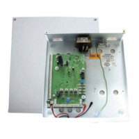
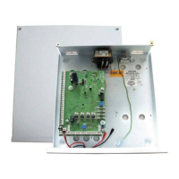
Visual representation of the 490X PCB connections.

Remote Keypads

Digi Modem

Control Panel Input (Zone Connection)

End of Line Zone Wiring

Wiring method using EOL resistors for secure zone detection.

Typical Wiring Modes

Typical ELF1

Wiring mode for detectors with relay output for fault/mask.

Typical ELF2

Wiring mode for detectors with transistor output for fault/mask.

Radio Zone Expander

3 RESETTING FACTORY DEFAULTS

Reset of the factory defaults and entering Engineer Mode

4 PROGRAMMING

Moving Around

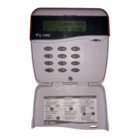
Navigation within the engineer programming mode.

Program Zones

Configuration of system zones, types, and descriptors.

Engineer Code

Setting and managing the engineer access code.

Service

Alarm Confirm

Confirm Time Window?

Setting the time window for alarm confirmation.

Confirm on Entry?

Configuring alarm confirmation during entry.

Sounder Mode?

Setting the sounder mode for confirmed/unconfirmed alarms.

Reset Mode?

Selecting the reset mode for alarms.

Common Options with Menu Numbers

Programming Zones

Zone Types available are:-

Detailed descriptions of available zone types and their functions.

Zone Attributes

Wiring Modes available are.

Testing Zones

Programming Setting Modes

Programming Bells; Sounders

Programming Keypad

Programming Digicom; Vo-Comm Off;On

Programming Linefault Modes

Programming Panic

Programming PGM2; 3; Timers

Programming Reset Modes

Programming Sounder Levels

Programming PGM1; Custom

Programming Engineer Code

Programming Diagnostics; Log

NovActive Description & Programming

Engineer Reset

Clearing ‘Test Fail’ Indication

5 SPECIFICATIONS

Power Input

Electrical power requirements for the control panel.

*Power Supply Rating

Detailed power supply and battery charging specifications.

4 WIRE CONTOUR RKP WIRING INFORMATION

GARDTEC GT490X Specifications

General IconGeneral
Tamper CircuitYes
Operating Temperature-10°C to +55°C
Zones8 zones
CommunicationPSTN
Power Supply230VAC
Backup Battery7Ah
Dimensions80 mm
CompatibilityGardtec peripherals

Related product manuals