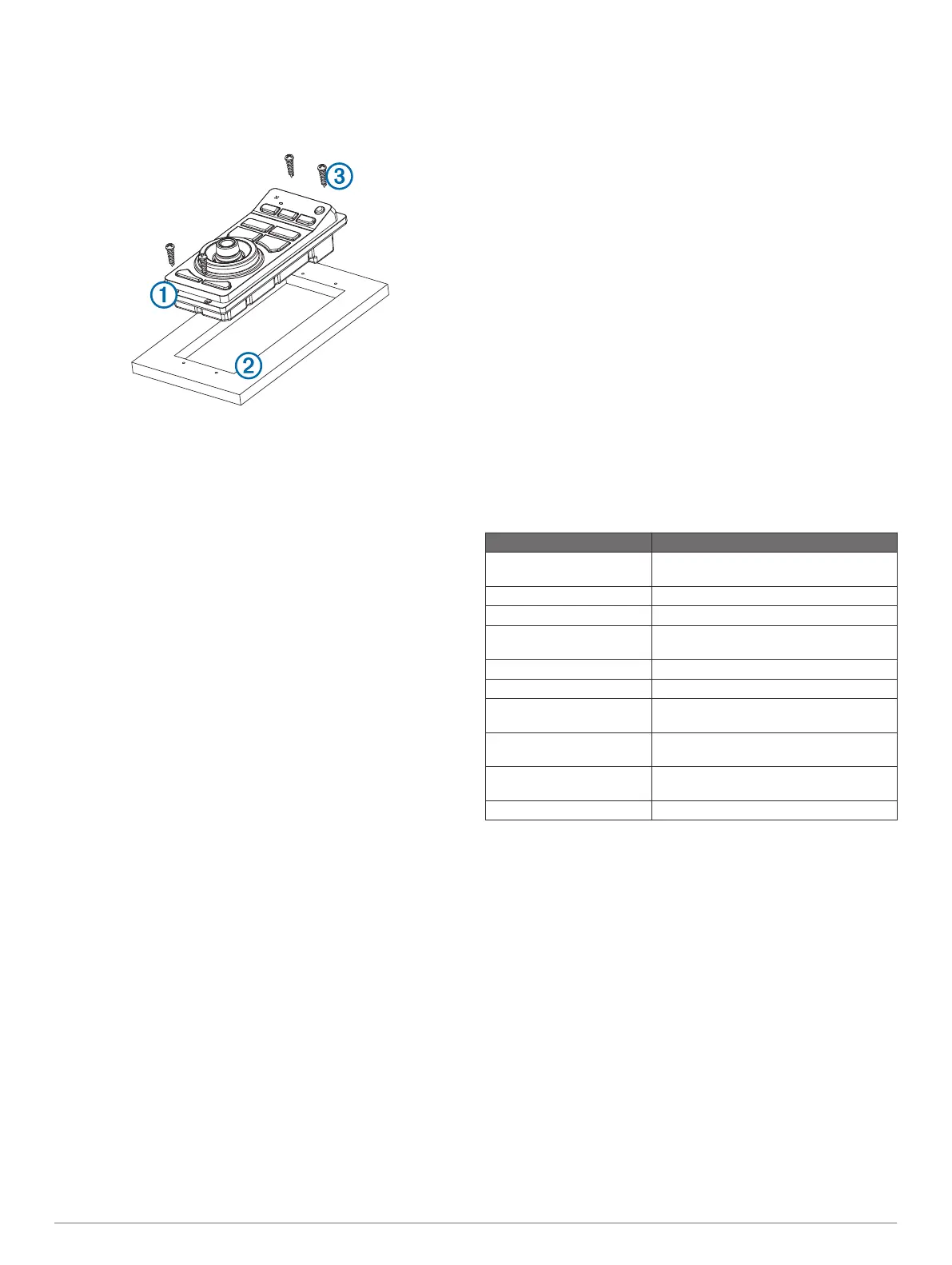
6
If necessary, use a file and sandpaper to refine the size of
the cutout.
7
After the device
À
fits correctly in the cutout, make sure the
mounting holes on the device line up with the pilot holes
Á
on
the template.
8
If the mounting holes on the device do not line up, mark the
new pilot-hole locations.
9
Using either a
3
/
32
in. (2.5 mm) drill bit, or drill bit appropriate
for the mounting surface, drill the pilot holes.
10
Remove the template from the mounting surface.
11
If you will not have access to the back of the device after you
mount it, connect all necessary cables to the device before
placing it into the cutout.
12
Place the device into the cutout.
13
Secure the device to the mounting surface using the included
screws
Â
.
14
Install the decorative bezel by snapping it in place around the
edges of the device.
Connection and Cable Considerations
• For easier cable routing, the power and Garmin Marine
Network cables are packaged without the locking rings
installed. You should route the cables before you install the
locking rings.
• After connecting a locking ring to a cable, you should make
sure the locking ring is securely connected and the o-ring is
in place so the power or data connection remains secure.
• The device should be connected to the same power source
as the other devices on the same Garmin Marine Network. If
this is not possible, all the devices must be connected to the
same ground.
Connecting the GRID
™
to the Garmin Marine Network
The GRID is not compatible with Garmin chartplotters prior to
the GPSMAP
®
8000 Series and the GPSMAP 8500.
The GRID does not need to be connected directly to the device
that you plan to control with the GRID. It can be assigned to any
compatible device connected to the same Garmin Marine
Network.
1
Connect the GRID to a Garmin device on the Garmin Marine
Network using a Garmin Marine Network cable.
2
After the rest of the devices in your Garmin Marine Network
are installed, use the software to assign the GRID to a
compatible Garmin device.
Pairing the GRID Remote Input Device with
the Chartplotter
Before you can use a GRID remote input device with a
chartplotter, you must pair the devices.
You can initiate the paring of the devices from the chartplotter or
from the GRID remote input device.
Pairing the GRID Device with the Chartplotter from
the GRID Device
1
On the GRID remote input device, press + and HOME at the
same time.
A selection page opens on all of the chartplotters on the
Garmin Marine Network.
2
Rotate the wheel on the GRID remote input device to
highlight Select on the chartplotter you want to control with
the GRID remote input device.
3
Press SELECT.
Pairing the GRID Device with the Chartplotter from
the Chartplotter
1
Select Settings > System > Station Information > GRID™
Pairing > Add.
2
On the GRID remote input device, press SELECT.
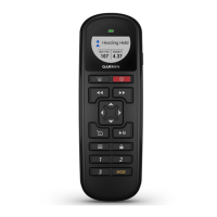
Rotating the GRID Joystick
For certain installation situations, you can rotate the orientation
of the GRID joystick.
1
Select Settings > Communications > Marine Network.
2
Select the GRID device.
GRID Specifications
Specification Measurement
Dimensions (W×H×D) 3
1
/
16
× 6
7
/
8
× 2
3
/
8
in. (77 × 174.8 × 60
mm)
Weight 9.1 oz. (258 g)
Temperature range From 5° to 158°F (from -15° to 70°C)
Material Fully gasketed, high-impact plastic,
waterproof to IEC 60529 IPX7 standards
Input power 10–35 Vdc
Fuse 7.5 A, 42 V fast-acting
Max. power usage at 10
Vdc
2.8 W
Typical current draw at 12
Vdc
100 mA
Max. current draw at 12
Vdc
280 mA
Compass-safe distance 14 in. (356 mm)
Installation Instructions 3