Do you have a question about the Garmin GSA 8X and is the answer not in the manual?
Provides the manual's purpose and the scope of the GFC 700 system installation.
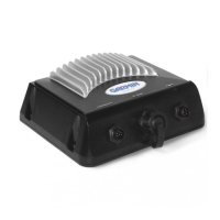
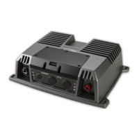
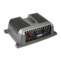
Details the electromechanical GSA 8X servo actuator and its functional components.
Describes the GSM 85(A) servo gearbox, its function, and variations.
Explains the combined operation of GSA 8X and GSM 85(A) in controlling aircraft axes.
Explains the serial communication interface between the GSA 8X and GIA units.
Lists EQF part numbers for GSA and GSM units for compliance verification.
Details unit dimensions and weights for GSA 8X and GSM 85(A) servo units.
Outlines operating temperature, altitude, and software versions for GSA 8X.
Provides maximum speed and torque specifications for GSA 8X models.
Details GSM 85(A) torque ranges and slip-clutch tolerances.
Specifies voltage range and power consumption for the GSA 8X servo actuator.
Lists TSO/ETSO compliance for GSA 80/81 and GSM 85/85A units.
Details deviations granted for TSO/ETSO compliance across specific environmental tests.
Outlines warranty terms, limitations, and procedures for Garmin avionics products.
Provides an overview of hardware for GSA 8X and GSM 85(A) installation.
Lists available unit part numbers for GSA 8X and GSM 85(A) servo units.
Lists available accessories required for GSA and GSM product installation.
Discusses interfacing, wiring, and general mechanical/electrical installation practices.
Details requirements for mounting the GSM 85(A) and GSA 8X to the airframe structure.
Explains the procedure and test fixture used for setting the slip-clutch.
Instructions for unpacking and inspecting the unit for shipment damage.
Guidelines for fabricating and installing wiring harnesses and connectors per FAA standards.
Detailed procedure for setting GSM 85(A) slip-clutch break-away torque values.
Guides for installing GSA 8X and GSM 85(A) units per aircraft-specific drawings.
Procedures for configuring and checking the system after installation completion.
Maintenance recommendations for GSA 8X and GSM 85(A) to ensure ongoing airworthiness.
Details the function of each pin on the GSA 8X J801 connector for I/O.
Describes the power connections and requirements for the GSA 8X unit.
Explains the RS-485 serial communication between GSA 8X and GIA units.
Details servo program inputs for configuring flight-control axis functionality.
Introduces outline and installation drawings for GSA and GSM series products.
Lists model numbers and corresponding applicable drawings for reference.
Provides dimensional outline for the GSA 80 servo actuator.
Provides dimensional outline for the GSA 81 (-00) servo actuator.
Provides dimensional outline for the GSA 81 (-10, -20) servo actuators.
Shows outline and mounting details for GSM 85 gearbox (1/16" cable, 2 bolt).
Continues outline and bracket cut-out dimensions for GSM 85 gearbox.
Shows outline and mounting details for GSM 85 gearbox (1/16" cable, 4 bolt).
Continues outline and bracket cut-out dimensions for GSM 85 gearbox.
Shows outline and mounting details for GSM 85 gearbox (3/32" cable).
Continues outline and cable wrap examples for GSM 85 gearbox.
Shows outline and mounting for GSM 85A gearbox (Continuous Travel).
Continues outline and mounting for GSM 85A gearbox (Continuous Travel).
Shows outline and mounting for GSM 85 gearbox (with Sprocket).
Continues outline and bracket cut-out for GSM 85 gearbox (with Sprocket).
Shows outline and mounting for GSM 85 Universal Hub gearbox.
Continues outline and hub dimensions for GSM 85 Universal Hub gearbox.
Shows outline and mounting for GSM 85A gearbox (3/32" cable).
Continues outline and cable wrap examples for GSM 85A gearbox.
Shows outline and mounting for GSM 85A gearbox (1/16" cable).
Continues outline and assembly views for GSM 85A gearbox.
Shows outline and mounting for GSM 85A gearbox (Universal Hub).
Shows outline and attachment for GSM 85A gearbox (Universal Hub, Optional Sprocket).
Shows outline and attachment for GSM 85A gearbox (Universal Hub, Generic Attachment).
Shows outline and mounting for GSM 85A gearbox (1/16" Cable, Continuous Travel).
Continues outline and assembly views for GSM 85A gearbox.
Provides cable wrap recommendations for spiral capstan GSM 85/85A.
Shows cable wrap recommendations for continuous travel gearboxes.
Illustrates servo motor and gearbox alignment perspective.
Shows typical wiring interconnects for GSA 8X in a three-servo setup.
| Brand | Garmin |
|---|---|
| Model | GSA 8X |
| Category | Marine Equipment |
| Language | English |