Do you have a question about the Garmin GSD 24 and is the answer not in the manual?
List of essential tools required for the installation process.
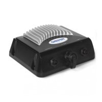
Guidelines for selecting an appropriate location to mount the adapter box.
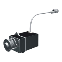
Steps to prepare the non-differential transducer cable for connection.
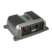
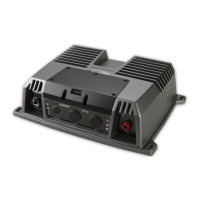
Procedure for connecting transducer wires to the adapter box wire block.
Technical details including dimensions, cable length, and water rating.
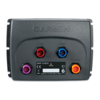
This document provides installation instructions for the Garmin 8-Pin Transducer Adapter Box, designed to connect non-differential 6-pin transducers (such as Garmin or Airmar models) to Garmin 8-pin sonar modules. It is crucial to note that this adapter box is not intended for use with Garmin differential 8-pin transducers, and users should not cut a Garmin differential 8-pin transducer cable; instead, it should be connected directly to the 8-pin port on the sonar module.
The primary function of the 8-Pin Transducer Adapter Box is to enable compatibility between older or non-differential 6-pin transducers and newer Garmin sonar modules that utilize an 8-pin differential input. This is achieved by providing a wire block within the adapter box where the wires from a cut 6-pin transducer cable can be connected according to specific functions (Depth +, Depth -, Shield, Ground, Temp +, XID, Speed power, Speed data). This allows the non-differential transducer's signals to be properly routed and interpreted by the differential sonar module. The adapter box essentially acts as a bridge, converting the wiring scheme to match the requirements of the 8-pin sonar module.
| Brand | Garmin |
|---|---|
| Model | GSD 24 |
| Category | Marine Equipment |
| Language | English |