Do you have a question about the Garmin GTX 320 ATC and is the answer not in the manual?
This manual provides procedures for repair and maintenance of the GARMIN GTX 320 ATC Transponder.
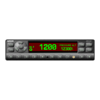
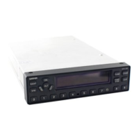
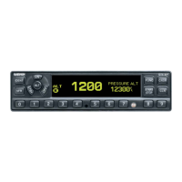
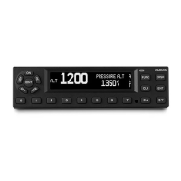
Describes the GTX 320 Transponder as part of the Air Traffic Secondary Radar Beacon System (ATCRBS).
Refers to the Installation and Operation Manual for detailed technical specifications of the GTX 320.
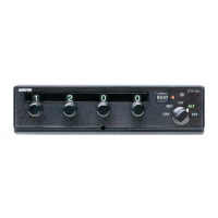
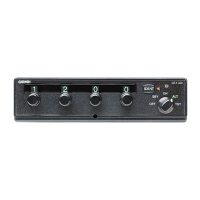
Details the GTX 320's two major assemblies: the Main PCB Assembly and the Front Subassembly.
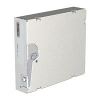
Lists the circuits contained within the Main PCB Assembly, which is not field repairable.
Lists the components of the Front Subassembly, which is designed for field replacement.
Recommends limiting field maintenance to front subassembly replacement and specific adjustments due to unit complexity.
Identifies special tools and test equipment essential for repairing the GTX 320, excluding standard equipment.
Lists the required special tools, including test harness, test panel, alignment tool, and antenna connector.
Describes fabrication requirements for the Test Panel and Test Harness needed for the test setup.
Explains the function of the alignment tool used for adjusting transmitter frequency and power output.
Details the installation of the blindmate BNC connector for the antenna test cable.
Introduces alignment and test procedures for identifying failures and after repairs.
States that field alignment of the GTX 320 is limited to adjusting the transmitter frequency only.
Lists the specific equipment required for performing the transmitter frequency adjustment.
Describes the typical alignment and test setup using connector J102 and the rear antenna connector.
Provides critical cautions for adjusting C620 and potential damage to the mixer during frequency adjustment.
Outlines various test procedures to be performed after completing transmitter frequency adjustment.
Refers to paragraph 3.2.1 for the list of test equipment.
Refers to figure 2-3 for the recommended test setup.
Details various functional and performance tests for the transponder unit.
Tests the approximate 5-second delay before the unit transmits upon being turned ON.
Verifies the reply transmission frequency range (1087-1093 MHz) on the ATC-1400A.
Checks if the transmitter power output meets the minimum requirement of 125 watts.
Describes the procedure for adjusting the Minimum Trigger Level (MTL) by varying RF levels.
Details oscilloscope settings and test parameters for checking reply pulse shape and timing.
Tests the transponder's response at varying RF levels to ensure a reply rate above 90%.
Tests the Automatic Overload Control feature by varying RF levels and PRF settings.
Tests the side lobe suppression capability by measuring reply rate at different RF levels.
Verifies the unit suppresses replies to interrogations during an external suppression pulse.
Tests the unit's response to external altitude encoder inputs, verifying pulse patterns.
Tests the IDENT function, verifying display changes and SPI pulse appearance on the oscilloscope.
Verifies illumination and power status in the OFF mode, ensuring only 'OFF' nomenclature is lit.
Checks illumination and lack of reply in Stand By (SBY) mode.
Checks illumination of 'ON' nomenclature and code digits in the ON mode.
Checks illumination of 'ALT' nomenclature and code digits in the Altitude mode.
Tests the TST mode, verifying nomenclature illumination and reply light operation.
Tests the reply light's behavior in ALT and TST modes under varying RF conditions.
Verifies code switches display correct numbers on test set and are mechanically stable.
Covers disassembly procedures specifically for removing a faulty Front Subassembly.
Outlines inspection steps before disassembly, checking screws, surfaces, and connectors.
Details steps for removing the Front Subassembly, including removing covers and flex strip.
Provides instructions for cleaning the transponder's external surface after reassembly.
| Brand | Garmin |
|---|---|
| Model | GTX 320 ATC |
| Category | Marine Radio |
| Language | English |